
Introductory Circuit Analysis (13th Edition)
13th Edition
ISBN: 9780133923605
Author: Robert L. Boylestad
Publisher: PEARSON
expand_more
expand_more
format_list_bulleted
Concept explainers
Videos
Textbook Question
Chapter 8, Problem 12P
Find the voltage
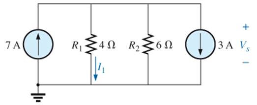
Fig. 8.114
Expert Solution & Answer
Want to see the full answer?
Check out a sample textbook solution
Students have asked these similar questions
Please no AI response.
I have uploaded the rules, please explain step by step and which rule you have applied
I have uploaded the rules, please explain step by step and which rule you have applied
Chapter 8 Solutions
Introductory Circuit Analysis (13th Edition)
Ch. 8 - For the network of Fig. 8.103: a. Find the...Ch. 8 - For the network of Fig. 8.104: a. Determine the...Ch. 8 - Find voltage Vs (with polarity) across the ideal...Ch. 8 - For the network in Fig. 8.106: a. Find voltage Vs....Ch. 8 - Find the voltage V3 and the current I2 for the...Ch. 8 - For the network in Fig. 8.108: a. Find the...Ch. 8 - Convert the voltage sources in Fig. 8.109 to...Ch. 8 - Convert the current sources in Fig. 8.110 to...Ch. 8 - For the network in Fig. 8.111: Find the current IL...Ch. 8 - For the configuration of Fig. 8.112: a. Convert...
Ch. 8 - For the network in Fig. 8.113: a. Replace all the...Ch. 8 - Find the voltage Vs and the current I1 for the...Ch. 8 - Convert the voltage sources in Fig. 8.115 to...Ch. 8 - For the network in Fig. 8.116, reduce the network...Ch. 8 - Using branch-current analysis, find the magnitude...Ch. 8 - For the network of Fig. 8.118: Determine the...Ch. 8 - Using branch-current analysis, find the current...Ch. 8 - Using branch-current analysis, find the current...Ch. 8 - For the network in Fig. 8.121: a. Write the...Ch. 8 - Using the general approach to mesh analysis,...Ch. 8 - Using the general approach to mesh analysis,...Ch. 8 - Using the general approach to mesh analysis,...Ch. 8 - Using the general approach to mesh analysis,...Ch. 8 - Determine the mesh currents for the network of...Ch. 8 - Write the mesh equations for the network of Fig....Ch. 8 - Write the mesh equations for thesss network of...Ch. 8 - Write the mesh currents for the network of Fig....Ch. 8 - Redraw the network of Fig. 8.125 in a manner that...Ch. 8 - For the transistor configuration in Fig. 8.126: a....Ch. 8 - Using the supermesh approach, find the current...Ch. 8 - Using the supermesh approach, find the current...Ch. 8 - Using the format approach to mesh analysis, write...Ch. 8 - Using the format approach to mesh analysis, write...Ch. 8 - Using the format approach to mesh analysis, write...Ch. 8 - Write the mesh equations for the network of Fig....Ch. 8 - Write the mesh equations for the network of Fig....Ch. 8 - a. Write the mesh equations for the network of...Ch. 8 - Write the mesh equations for the network of Fig....Ch. 8 - Write the mesh equations for the network of Fig....Ch. 8 - a. Write the mesh equations for the network of...Ch. 8 - a. Write the nodal equations using the general...Ch. 8 - Write the nodal equations using the general...Ch. 8 - a. Write the nodal equations using the general...Ch. 8 - a. Write the nodal equations for the network of...Ch. 8 - a. Write the nodal equations for the network of...Ch. 8 - a. Write the nodal equations for the network of...Ch. 8 - Write the nodal equations for the network of Fig....Ch. 8 - Write the nodal equations for the network of Fig....Ch. 8 - Write the nodal equations for the network of Fig....Ch. 8 - Using the supernode approach, determine the nodal...Ch. 8 - Using the supernode approach, determine the nodel...Ch. 8 - Determine the nodal voltages of Fig. 8.130 using...Ch. 8 - Convert the voltage source of Fig 8.131 to a...Ch. 8 - Convert the voltage source of Fig. 8.136 to a...Ch. 8 - Apply the format approach of nodal analysis to the...Ch. 8 - Using the format approach, find the nodal voltages...Ch. 8 - Convert the voltage sources of Fig. 8.129 to...Ch. 8 - For the network of Fig. 8.135: a. Convert the...Ch. 8 - For the bridge network in Fig. 8.141: a. Write the...Ch. 8 - For the network in Fig. 8.141: a. Write the nodal...Ch. 8 - For the bridge in Fig. 8.142: a. Write the mesh...Ch. 8 - For the bridge network in Fig. 8.142: a. Write the...Ch. 8 - Determine the current through the source resistor...Ch. 8 - Repeat Problem 63 for the network of Fig. 8.144....Ch. 8 - Using a -Y or Y- conversion, find the current I...Ch. 8 - Convert the of 6.8 k resistors in Fig. 8.146 to...Ch. 8 - For the network of Fig. 8.147, find the current I...Ch. 8 - a. Using a -Y or Y- conversion, find the current...Ch. 8 - The network of Fig. 8.149 is very similar to the...Ch. 8 - a. Replace the TT configuration in Fig.8.150...Ch. 8 - Using Y or Yconversion, determine the total...Ch. 8 - Using schematics, find the current through each...Ch. 8 - Using schematics, find the mesh currents for the...Ch. 8 - Using schematics, determine the nodal voltages for...
Additional Engineering Textbook Solutions
Find more solutions based on key concepts
What types of coolant are used in vehicles?
Automotive Technology: Principles, Diagnosis, And Service (6th Edition) (halderman Automotive Series)
The solid steel shaft AC has a diameter of 25 mm and is supported by smooth bearings at D and E. It is coupled ...
Mechanics of Materials (10th Edition)
Why is the study of database technology important?
Database Concepts (8th Edition)
Assume a telephone signal travels through a cable at two-thirds the speed of light. How long does it take the s...
Electric Circuits. (11th Edition)
This optional Google account security feature sends you a message with a code that you must enter, in addition ...
SURVEY OF OPERATING SYSTEMS
The ____________ is always transparent.
Web Development and Design Foundations with HTML5 (8th Edition)
Knowledge Booster


Learn more about
Need a deep-dive on the concept behind this application? Look no further. Learn more about this topic, electrical-engineering and related others by exploring similar questions and additional content below.Similar questions
- I have uploaded the rules, please explain step by step and which rule you have appliedarrow_forwardUsing the CCS Compiler method to solve this question Write a PIC16F877A program that flash ON the 8-LED's connected to port-B by using two switches connected to port-D (Do & D₁) as shown in figure below, according to the following scenarios: (Hint: Use 500ms delay for each case with 4MHz frequency) 1. When Do=1 then B₁,B3,B7 are ON. 2. When Do 0 then Bo,B2, B4, B5, B6 are ON. 3. When D₁=1 then B4,B,,B6,B7 are ON. 4. When D₁-0 then Bo,B1,B2,B3 are ON.arrow_forwardUse the ramp generator circuit in Fig. B2a to generate the waveform shown in Fig. B2b. Write four equations relating resistors R1, R2, R3, capacitor C and voltages Vs, VR and VA.to the waveform parameters T₁, T, Vcm and Vm- If R = R2 = R3, R₁ = 2R, C = 1 nF, Vcm = 2 V and Vm = 1 V, T₁ = 2 μs and T = 10 μs solve for the values of R, Vs, VR and VA using your equations from part a(i). VR C +VA R3 V₂ Vo мат R1 VsO+ V₁ R₂ Figure B2a Vout Vcm+Vm Vcm Vcm-Vm 0 T₁ T 2T time Figure B2barrow_forward
- The circuit in Figure B1a is a common analogue circuit block. Explain why you would need such a circuit. Draw another circuit in which you use the current flowing in this loop to bias a common source amplifier. This circuit is not ideal for standard CMOS technologies due to threshold shift. Why? Draw an improved version of this circuit to make it better. VDD (W)P MA M3. (), REF (쁜)~ M₁ M2 lout 시~ Rsarrow_forward23bcarrow_forwardDraw the small-signal equivalent circuit of a single transistor amplifier given in figure B1b. Assume the current source to be ideal. Determine the Open-loop transfer function, pole frequency and gain-bandwidth product all in terms of transistor parameters 9m, To and CL. If the load capacitance is 1pF and the necessary unity gain frequency is 600MHz, find the gm for this transistor. V₁ V₁ CLarrow_forward
arrow_back_ios
SEE MORE QUESTIONS
arrow_forward_ios
Recommended textbooks for you
 Introductory Circuit Analysis (13th Edition)Electrical EngineeringISBN:9780133923605Author:Robert L. BoylestadPublisher:PEARSON
 Delmar's Standard Textbook Of ElectricityElectrical EngineeringISBN:9781337900348Author:Stephen L. HermanPublisher:Cengage Learning
 Programmable Logic ControllersElectrical EngineeringISBN:9780073373843Author:Frank D. PetruzellaPublisher:McGraw-Hill Education
 Fundamentals of Electric CircuitsElectrical EngineeringISBN:9780078028229Author:Charles K Alexander, Matthew SadikuPublisher:McGraw-Hill Education
 Electric Circuits. (11th Edition)Electrical EngineeringISBN:9780134746968Author:James W. Nilsson, Susan RiedelPublisher:PEARSON
 Engineering ElectromagneticsElectrical EngineeringISBN:9780078028151Author:Hayt, William H. (william Hart), Jr, BUCK, John A.Publisher:Mcgraw-hill Education,
Introductory Circuit Analysis (13th Edition)
Electrical Engineering
ISBN:9780133923605
Author:Robert L. Boylestad
Publisher:PEARSON
Delmar's Standard Textbook Of Electricity
Electrical Engineering
ISBN:9781337900348
Author:Stephen L. Herman
Publisher:Cengage Learning
Programmable Logic Controllers
Electrical Engineering
ISBN:9780073373843
Author:Frank D. Petruzella
Publisher:McGraw-Hill Education
Fundamentals of Electric Circuits
Electrical Engineering
ISBN:9780078028229
Author:Charles K Alexander, Matthew Sadiku
Publisher:McGraw-Hill Education
Electric Circuits. (11th Edition)
Electrical Engineering
ISBN:9780134746968
Author:James W. Nilsson, Susan Riedel
Publisher:PEARSON
Engineering Electromagnetics
Electrical Engineering
ISBN:9780078028151
Author:Hayt, William H. (william Hart), Jr, BUCK, John A.
Publisher:Mcgraw-hill Education,
Kirchhoff's Rules of Electrical Circuits; Author: Flipping Physics;https://www.youtube.com/watch?v=d0O-KUKP4nM;License: Standard YouTube License, CC-BY