
Introductory Circuit Analysis (13th Edition)
13th Edition
ISBN: 9780133923605
Author: Robert L. Boylestad
Publisher: PEARSON
expand_more
expand_more
format_list_bulleted
Concept explainers
Videos
Textbook Question
Chapter 8, Problem 63P
Determine the current through the source resistor
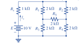
Fig. 8.143
Expert Solution & Answer
Want to see the full answer?
Check out a sample textbook solution
Students have asked these similar questions
Name the circuit below? The output voltage is initially zero and the pulse width is
200 μs. Find the Vout and draw the output waveform?
+2.5 V
V
247
-2.5 V
C
0.01 F
Ri
W
10 ΚΩ
Please work out
Find Vfinal when Vs
up
and Vs V. Which LED will light
in each case? Red or Green? Justify your answers. Fill the
table below.
Vs
8 ΚΩ
Vos
Χρι
+
3 ΚΩ
www
6 ΚΩ
ww
4 ΚΩ Yo
www
Vo
Vec-12 V
Nol
V final
Vm
w
3 ΚΩ
5 V
38 ΚΩ
R= 1 kQ
V
-12 V
Red LED
Green
LED
Vs
Vo
Vfinal
Which LED is ON?
V
Chapter 8 Solutions
Introductory Circuit Analysis (13th Edition)
Ch. 8 - For the network of Fig. 8.103: a. Find the...Ch. 8 - For the network of Fig. 8.104: a. Determine the...Ch. 8 - Find voltage Vs (with polarity) across the ideal...Ch. 8 - For the network in Fig. 8.106: a. Find voltage Vs....Ch. 8 - Find the voltage V3 and the current I2 for the...Ch. 8 - For the network in Fig. 8.108: a. Find the...Ch. 8 - Convert the voltage sources in Fig. 8.109 to...Ch. 8 - Convert the current sources in Fig. 8.110 to...Ch. 8 - For the network in Fig. 8.111: Find the current IL...Ch. 8 - For the configuration of Fig. 8.112: a. Convert...
Ch. 8 - For the network in Fig. 8.113: a. Replace all the...Ch. 8 - Find the voltage Vs and the current I1 for the...Ch. 8 - Convert the voltage sources in Fig. 8.115 to...Ch. 8 - For the network in Fig. 8.116, reduce the network...Ch. 8 - Using branch-current analysis, find the magnitude...Ch. 8 - For the network of Fig. 8.118: Determine the...Ch. 8 - Using branch-current analysis, find the current...Ch. 8 - Using branch-current analysis, find the current...Ch. 8 - For the network in Fig. 8.121: a. Write the...Ch. 8 - Using the general approach to mesh analysis,...Ch. 8 - Using the general approach to mesh analysis,...Ch. 8 - Using the general approach to mesh analysis,...Ch. 8 - Using the general approach to mesh analysis,...Ch. 8 - Determine the mesh currents for the network of...Ch. 8 - Write the mesh equations for the network of Fig....Ch. 8 - Write the mesh equations for thesss network of...Ch. 8 - Write the mesh currents for the network of Fig....Ch. 8 - Redraw the network of Fig. 8.125 in a manner that...Ch. 8 - For the transistor configuration in Fig. 8.126: a....Ch. 8 - Using the supermesh approach, find the current...Ch. 8 - Using the supermesh approach, find the current...Ch. 8 - Using the format approach to mesh analysis, write...Ch. 8 - Using the format approach to mesh analysis, write...Ch. 8 - Using the format approach to mesh analysis, write...Ch. 8 - Write the mesh equations for the network of Fig....Ch. 8 - Write the mesh equations for the network of Fig....Ch. 8 - a. Write the mesh equations for the network of...Ch. 8 - Write the mesh equations for the network of Fig....Ch. 8 - Write the mesh equations for the network of Fig....Ch. 8 - a. Write the mesh equations for the network of...Ch. 8 - a. Write the nodal equations using the general...Ch. 8 - Write the nodal equations using the general...Ch. 8 - a. Write the nodal equations using the general...Ch. 8 - a. Write the nodal equations for the network of...Ch. 8 - a. Write the nodal equations for the network of...Ch. 8 - a. Write the nodal equations for the network of...Ch. 8 - Write the nodal equations for the network of Fig....Ch. 8 - Write the nodal equations for the network of Fig....Ch. 8 - Write the nodal equations for the network of Fig....Ch. 8 - Using the supernode approach, determine the nodal...Ch. 8 - Using the supernode approach, determine the nodel...Ch. 8 - Determine the nodal voltages of Fig. 8.130 using...Ch. 8 - Convert the voltage source of Fig 8.131 to a...Ch. 8 - Convert the voltage source of Fig. 8.136 to a...Ch. 8 - Apply the format approach of nodal analysis to the...Ch. 8 - Using the format approach, find the nodal voltages...Ch. 8 - Convert the voltage sources of Fig. 8.129 to...Ch. 8 - For the network of Fig. 8.135: a. Convert the...Ch. 8 - For the bridge network in Fig. 8.141: a. Write the...Ch. 8 - For the network in Fig. 8.141: a. Write the nodal...Ch. 8 - For the bridge in Fig. 8.142: a. Write the mesh...Ch. 8 - For the bridge network in Fig. 8.142: a. Write the...Ch. 8 - Determine the current through the source resistor...Ch. 8 - Repeat Problem 63 for the network of Fig. 8.144....Ch. 8 - Using a -Y or Y- conversion, find the current I...Ch. 8 - Convert the of 6.8 k resistors in Fig. 8.146 to...Ch. 8 - For the network of Fig. 8.147, find the current I...Ch. 8 - a. Using a -Y or Y- conversion, find the current...Ch. 8 - The network of Fig. 8.149 is very similar to the...Ch. 8 - a. Replace the TT configuration in Fig.8.150...Ch. 8 - Using Y or Yconversion, determine the total...Ch. 8 - Using schematics, find the current through each...Ch. 8 - Using schematics, find the mesh currents for the...Ch. 8 - Using schematics, determine the nodal voltages for...
Knowledge Booster


Learn more about
Need a deep-dive on the concept behind this application? Look no further. Learn more about this topic, electrical-engineering and related others by exploring similar questions and additional content below.Similar questions
- Circuits help please solve and explain. Question in images providedarrow_forward+ V 6.2 A 1.2 A S R 4 Ω Find the source voltage Vs 0.8 Aarrow_forwardDetermine i(t) for t≥ 0 given that the circuit below had been in steady state for a long time prior to t = 0. Also, I₁ = 1 5 A, R₁ =22, R2 =10 Q2, R3 = 32, R4 =7 2, and L=0.15 H. Also fill the table. m L ww R2 t = 0 R₁ 29 R3 R4 Time 0 iL(t) 0 8arrow_forward
- Find the Thévenin equivalent circuit for the portions of the networks in Figure external to the elements between points a and b. a R₁ 2002 I = 0.1 A 0° Xc : 32 Ω R2 = 6802 20 Ω фъarrow_forwardFind the Norton equivalent circuit for the network external to the elements between a and b for the networks in Figure. E1 = 120 V Z 0° R ww 10 Ω Xc XL · 000 802 802 ① I = 0.5 AZ 60° ZL barrow_forwardUsing superposition, determine the current through inductance XL for each network in Figure I = 0.3 A 60° XL 000 802 XC 502 Ω E 10 V0° =arrow_forward
- Find the Thévenin equivalent circuit for the portions of the networks in Figure external to the elements between points a and b. E = 20 VZ0° + R ww 2 ΚΩ Хо XL 000 6ΚΩ 3 ΚΩ b RLarrow_forwardWhat percentage of the full-load current of a thermally protected continuous-duty motor of more than one Hp can the trip current be, if the full-load current is 15 amperes? Ο 122 Ο 140 156 O 170arrow_forwardQ3arrow_forward
arrow_back_ios
SEE MORE QUESTIONS
arrow_forward_ios
Recommended textbooks for you
 Delmar's Standard Textbook Of ElectricityElectrical EngineeringISBN:9781337900348Author:Stephen L. HermanPublisher:Cengage Learning
Delmar's Standard Textbook Of Electricity
Electrical Engineering
ISBN:9781337900348
Author:Stephen L. Herman
Publisher:Cengage Learning
Kirchhoff's Rules of Electrical Circuits; Author: Flipping Physics;https://www.youtube.com/watch?v=d0O-KUKP4nM;License: Standard YouTube License, CC-BY