
Bundle: Mechanics Of Materials, Loose-leaf Version, 9th + Mindtap Engineering, 1 Term (6 Months) Printed Access Card
9th Edition
ISBN: 9781337594318
Author: Barry J. Goodno; James M. Gere
Publisher: Cengage Learning
expand_more
expand_more
format_list_bulleted
Videos
Textbook Question
Chapter 6, Problem 6.3.7P
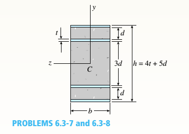
The cross section of a beam made of thin strips of aluminum separated by a lightweight plastic is shown in the figure. The beam has width b = 3.0 in., the aluminum strips have thickness t = 0.1 in., and the plastic segments have heights d = 1.2 in. and 3d = 3.6 in. The total height of the beam is h = 6.4 in.
The moduli of elasticity for the aluminum and plastic are EM= 11 X 106 psi and Ep= 440 X 10* psi, respectively.
Determine the maximum stresses trAiand
Expert Solution & Answer

Trending nowThis is a popular solution!

Students have asked these similar questions
Calculate the compression ratio of an engine with a stroke of 4.2inches a bore of 4.5 inches and a clearance volume of 6.15 cubic inches. Discuss whether or not this is a realistic compression ratio for a street engine and what octane rating of fuel it would need to run correctly
Draw the free-body diagram for the pinned assembly shown. Find the magnitude of the forces
acting on each member of the assembly.
1500 N
1500 N
C
45°
45°
45°
45°
1000 mm
An elastic bar of length L spins with angular velocity ω about an axis, as shown in the figure below. The radial acceleration at a generic point x along the bar is a(x) = ω 2 x. Due to this radial acceleration, the bar stretches along x with displacement function u(x). The displacement u(x) is governed by the following equations: ( d dx (σ(x)) + ρa(x) = 0 PDE σ(x) = E du dx Hooke’s law (1) where σ(x) is the axial stress in the rod, ρ is the mass density, and E is the (constant) Young’s modulus. The bar is pinned on the rotation axis at x = 0, and it is free at x = L.
Determine:1. Appropriate BCs for this physical problem.2. The displacement function u(x).3. The stress function σ(x).
Chapter 6 Solutions
Bundle: Mechanics Of Materials, Loose-leaf Version, 9th + Mindtap Engineering, 1 Term (6 Months) Printed Access Card
Ch. 6 - A composite beam is constructed using a steel...Ch. 6 - A wood beam is strengthened using two steel plates...Ch. 6 - A composite beam consisting of fiberglass faces...Ch. 6 - A wood beam with cross-sectional dimensions 200 mm...Ch. 6 - A hollow box beam is constructed with webs of...Ch. 6 - A r o lukI f/frm f «m t ub e of ou t sid e d ia...Ch. 6 - A beam with a guided support and 10-ft span...Ch. 6 - A plastic-lined steel pipe has the cross-sectional...Ch. 6 - The cross section of a sand wie h beam consisting...Ch. 6 - The cross section of a sandwich beam consisting of...
Ch. 6 - A bimetallic beam used in a temperature-control...Ch. 6 - A simply supported composite beam 3 m long carries...Ch. 6 - A simply supported wooden I-beam with a 12-ft span...Ch. 6 - -14 A simply supported composite beam with a 3.6 m...Ch. 6 - -15 A composite beam is constructed froma wood...Ch. 6 - A wood beam in a historic theater is reinforced...Ch. 6 - Repeat Problem 6.2-1 but now assume that the steel...Ch. 6 - Repeat Problem 6.2-17 but now use a...Ch. 6 - A sandwich beam having steel faces enclosing a...Ch. 6 - A wood beam 8 in. wide and 12 in. deep (nominal...Ch. 6 - A simple beam of span length 3.2 m carries a...Ch. 6 - A simple beam that is 18 ft long supports a...Ch. 6 - The composite beam shown in the figure is simply...Ch. 6 - The cross section of a beam made of thin strips of...Ch. 6 - Consider the preceding problem if the beam has...Ch. 6 - A simple beam thai is IS ft long supports a...Ch. 6 - The cross section of a composite beam made of...Ch. 6 - A beam is constructed of two angle sections, each...Ch. 6 - The cross section of a bimetallic strip is shown...Ch. 6 - A W 12 x 50 steel wide-flange beam and a segment...Ch. 6 - A reinforced concrete beam (see figure) is acted...Ch. 6 - A reinforced concrete T-beam (see figure) is acted...Ch. 6 - A reinforced concrete slab (see figure) is...Ch. 6 - A wood beam reinforced using two channels is...Ch. 6 - A wood beam reinforced by an aluminum channel...Ch. 6 - A beam with a rectangular cross section supports...Ch. 6 - A wood beam with a rectangular cross section (see...Ch. 6 - Solve the preceding problem for the following...Ch. 6 - A simply supported wide-flange beam of span length...Ch. 6 - Solve the preceding problem using the fol...Ch. 6 - A wood cantilever beam with a rectangular cross...Ch. 6 - Solve the preceding problem for a cantilever beam...Ch. 6 - A 2-m-long cantilever beam is constructed using a...Ch. 6 - A wood beam AB with a rectangular cross section (4...Ch. 6 - A steel beam of I-section (see figure) is simply...Ch. 6 - A cantilever beam with a wide-flange cross section...Ch. 6 - Solve the preceding problem using a W 310 x 129...Ch. 6 - A cantilever beam of W 12 × 14 section and length...Ch. 6 - A cantilever beam built up from two channel...Ch. 6 - A built-Lip I-section steel beam with channels...Ch. 6 - Repeat Problem 6.4-14 but use the configuration of...Ch. 6 - A beam with a channel section is subjected to a...Ch. 6 - A beam with a channel section is subjected to a...Ch. 6 - An angle section with equal legs is subjected to a...Ch. 6 - An angle section with equal legs is subjected to a...Ch. 6 - A beam made up all woun equal leg angles is...Ch. 6 - The Z-section of Example D-7 is subjected to M = 5...Ch. 6 - The cross section of a steel beam is constructed...Ch. 6 - The cross section of a steel beam is shown in the...Ch. 6 - A beam with a semicircular cross section of radius...Ch. 6 - .10 A built-up bourn supporting a condominium...Ch. 6 - Asteelpost (E = 30 × 106 psi) having thickness t =...Ch. 6 - A C 200 x 17.1 channel section has an angle with...Ch. 6 - A cold-formed steel section is made by folding a...Ch. 6 - A simple beam with a W 10 x 30 wide-flange cross...Ch. 6 - Solve the preceding problem for a W 250 × 44.8...Ch. 6 - A beam of wide-flange shape, W 8 x 28, has the...Ch. 6 - Solve the preceding problem for a W 200 × 41,7...Ch. 6 - Calculate the distance e from the cent crime of...Ch. 6 - Calculate the distance e from the centerline of...Ch. 6 - The cross section of an unbalanced wide-flange...Ch. 6 - The cross section of an unbalanced wide-flange...Ch. 6 - The cross section of a channel beam with double...Ch. 6 - The cross section of a slit circular tube of...Ch. 6 - The cross section of a slit square tube of...Ch. 6 - The cross section of a slit rectangular tube of...Ch. 6 - A U-shaped cross section of constant thickness is...Ch. 6 - Derive the following formula for the distance e...Ch. 6 - Derive the following formula for the distance e...Ch. 6 - The cross section of a sign post of constant...Ch. 6 - A cross section in the shape of a circular arc of...Ch. 6 - Determine the shape factor f for a cross section...Ch. 6 - (a) Determine the shape factor/for a hollow...Ch. 6 - A propped cantilever beam of length L = 54 in....Ch. 6 - A steel beam of rectangular cross section is 40 mm...Ch. 6 - .5 Calculate the shape factor j for the...Ch. 6 - Solve the preceding problem for a wide-flange beam...Ch. 6 - Determine the plastic modulus Z and shape...Ch. 6 - Prob. 6.10.8PCh. 6 - Prob. 6.10.9PCh. 6 - Prob. 6.10.10PCh. 6 - A hollow box beam with height h = 16 in,, width h...Ch. 6 - Solve the preceding problem for a box beam with...Ch. 6 - A hollow box beam with height h = 9.5 in., inside...Ch. 6 - Solve the preceding problem for a box beam with...Ch. 6 - The hollow box beam shown in the figure is...Ch. 6 - Prob. 6.10.16PCh. 6 - Prob. 6.10.17PCh. 6 - A singly symmetric beam with a T-section (see...Ch. 6 - A wide-flange beam with an unbalanced cross...Ch. 6 - .20 Determine the plastic moment Mpfor beam having...
Knowledge Booster


Learn more about
Need a deep-dive on the concept behind this application? Look no further. Learn more about this topic, mechanical-engineering and related others by exploring similar questions and additional content below.Similar questions
- With reference to the given figure: a) Draw a free-body diagram of the structure supporting the pulley. b) Draw shear and bending moment diagrams for both the vertical and horizontal portions of the structure. 48 in. 100 lb 12 in. Cable 27 in. 12-in. pulley radius 100 lb Cablearrow_forwardConsider a standard piston engine . Draw a free body diagram of the piston. Then:a) For an A SI engine with a 100 mm bore at an instantaneous cylinder pressure of 42 bar i. Calculate the level of the combustion gas loading force on the wrist pin in kN. b) Repeat this calculationfor a forced-induction Diesel engine with a 145 mm boreat a cylinder pressure of 115 bararrow_forwardA punch press with flywheel adequate to minimize speed fluctuation produces 120 punching strokes per minute, each providing an average force of 2000 N over a stroke of 50 mm. The press is driven through a gear reducer by a shaft rotating 200 rpm. Overall efficiency is 80%. a) What power (W) is transmitted through the shaft? b) What average torque is applied to the shaft?arrow_forward
- 1.58 The crankshaft of a single-cylinder air compressor rotates 1800 rpm. The piston area is 2000 mm2 and the piston stroke is 50 mm. Assume a simple “idealized” case where the average gas pressure acting on the piston during the compression stroke is 1 MPa, and pressure during the intake stroke is negligible. The compressor is 80% efficient. A flywheel provides adequate control of the speed fluctuation. a) What motor power (kW) is required to drive the crankshaft? b) What torque is transmitted through the crankshaft?arrow_forward28. The shaft shown in Figure P5-28 is supported by bear- ings at each end, which have bores of 20.0 mm. Design the shaft to carry the given load if it is steady and the shaft is stationary. Make the dimension a as large as pos- sible while keeping the stress safe. Determine the required d 20 mm 5.4 kN d D = ? Length not to scale -α = = -125 mm 20 mm a = -250 mm- FIGURE P5-28 (Problems 28, 29, and 30)arrow_forwardThe motor shown operates at constant speed and develops a torque of 100 lb-in during normal operation. Attached to the motor shaft is a gear reducer of ratio 5:1, that is, the reducer output shaft rotates in the same direction as the motor but at one-fifth motor speed. Rotation of the reducer housing is prevented by the "torque arm" pin-connected at each end as shown. The reducer output shaft drives the load through a flexible coupling. Neglecting gravity and friction, what loads are applied to (a) the torque arm, (b) the motor output shaft, and (c) the reducer output shaft? Motor Gear reducer Flexible coupling (To load) Torque arm- Torque arm Reducer output shaft Motor Reducer Shaft rotationarrow_forward
- Please can you help with ten attatched question?arrow_forwardAn AISI 1018 steel ball with 1.100-in diameter is used as a roller between a flat plate made from 2024 T3 aluminum and a flat table surface made from ASTM No. 30 gray cast iron. Determine the maximum amount of weight that can be stacked on the aluminum plate without exceeding a maximum shear stress of 19.00 kpsi in any of the three pieces. Assume the figure given below, which is based on a typical Poisson's ratio of 0.3, is applicable to estimate the depth at which the maximum shear stress occurs for these materials. 1.0 0.8 Ratio of stress to Pmax 0.4 90 0.6 στ Tmax 0.2 0.5a a 1.5a 2a 2.5a За Distance from contact surface The maximum amount of weight that can be stacked on the aluminum plate is lbf.arrow_forwardA carbon steel ball with 27.00-mm diameter is pressed together with an aluminum ball with a 36.00-mm diameter by a force of 11.00 N. Determine the maximum shear stress and the depth at which it will occur for the aluminum ball. Assume the figure given below, which is based on a typical Poisson's ratio of 0.3, is applicable to estimate the depth at which the maximum shear stress occurs for these materials. 1.0 0.8 Ratio of stress to Pma 9 0.6 στ 24 0.4 Tmax 0.2 0 0.5a a 1.5a Z 2a 2.5a За Distance from contact surface The maximum shear stress is determined to be MPa. The depth in the aluminum ball at which the maximum shear stress will occur is determined to be [ mm.arrow_forward
- Show all work pleasearrow_forwardDraw top, side, front view With pen(cil) and paper Multi view drawing and handwriting all of itarrow_forwardA wheel of diameter 150.0 mm and width 37.00 mm carrying a load 2.200 kN rolls on a flat rail. Take the wheel material as steel and the rail material as cast iron. Assume the figure given, which is based on a Poisson's ratio of 0.3, is applicable to estimate the depth at which the maximum shear stress occurs for these materials. At this critical depth, calculate the Hertzian stresses σr, σy, σz, and Tmax for the wheel. 1.0 0.8 0, т Ratio of stress to Pmax 0.4 0.6 90 69 0.2 0.5b b 1.5b Tmax 2b Distance from contact surface The Hertizian stresses are as follows: 02 = or = -23.8 psi for the wheel =| necessary.) σy for the wheel =| MPa σz for the wheel = MPa V4 for the wheel = | MPa 2.5b ཡི 3b MPa (Include a minus sign ifarrow_forward
arrow_back_ios
SEE MORE QUESTIONS
arrow_forward_ios
Recommended textbooks for you
 Mechanics of Materials (MindTap Course List)Mechanical EngineeringISBN:9781337093347Author:Barry J. Goodno, James M. GerePublisher:Cengage Learning
Mechanics of Materials (MindTap Course List)
Mechanical Engineering
ISBN:9781337093347
Author:Barry J. Goodno, James M. Gere
Publisher:Cengage Learning
Mechanics of Materials Lecture: Beam Design; Author: UWMC Engineering;https://www.youtube.com/watch?v=-wVs5pvQPm4;License: Standard Youtube License