
Videos
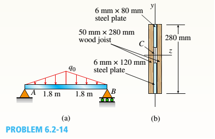
-14 A simply supported composite beam with a 3.6 m span supports a triangularly distributed load of peak intensity q0at mid-span (see figure part a). The beam is constructed of two wood joists, each 50 mm x 280 mm, fastened to two steel plates, one of dimensions 6 mm × 80 mm and the lower plate of dimensions 6 mm x 120mm (see figure part b). The modulus of elasticity for the wood is 11 GPa and for the steel is 210 GPa.
If the allowable stresses are 7 MPa for the wood and 120 MPa for the steel, find the allowable peak load intensity q0maxwhen the beam is bent about the z axis. Neglect the weight of the beam.
The peak maximum load intensity
Answer to Problem 6.2.14P
The peak maximum load intensity
Explanation of Solution
Given Information:
The given figure,
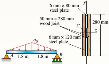
A supported beam with the span of 3.6m supports a load that is triangularly distributed with the peak intensity at the mid span. The two wood joists of the beam each measuring 50mm*280mm that is fastened to steel plates of two that has dimensions of 6mm*80mm and 6mm*120mm. The wood elasticity modulus is 11GPa and for steel it is 210GPa.
By the given equation the neutral axis location is determined,
Where,
Using the figure we have,
The distance between the section 1centroid and composite section neutral axis is,
The distance between the section 2 centroid and composite section neutral axis is,
The distance between the section 3 centroid and composite section neutral axis is,
The distance between the section 4 centroid and composite section neutral axis is,
Section 1 area
Section 2 area
Section 3 area
Section 4 area
Substituting the given values in (1)
Assume the load is symmetric at the span centre. So at point A the reaction is half the total load
The bending moment maximum is seen at the mid span as the symmetric load is at the span centre.
In the diagram the beam at the mid span is cut and the equilibrium cut at the left side is considered. Here M is considered as the bending moment maximum.
The right section moment is given as,
With the help of parallel axis theorem the steel section’s second moment of inertia at the neutral axis is determined.
With the help of parallel axis theorem the wooden section’s second moment of inertia at the neutral axis is determined.
The equation of the flexural stress at the maximum of the steel that has the top layer,
Substituting the values we have,
As the top layer of the steel is compressive the negative sign is given in the equation (2)
The equation of the flexural stress at the maximum of the steel that has the bottom layer,
The equation of the flexural stress at the maximum of the wood that has the top layer,
The equation of the flexural stress at the maximum of the wood that has the bottom layer,
The load with the lowest magnitude is selected from the equations (2), (3), (4), (5)
Conclusion:
Thus, the peak maximum load intensity is calculated by substituting section areas in equation 1.
Want to see more full solutions like this?
Chapter 6 Solutions
Bundle: Mechanics Of Materials, Loose-leaf Version, 9th + Mindtap Engineering, 1 Term (6 Months) Printed Access Card


- Access Pearson mylabmastering.pearson.com P Pearson MyLab and Mastering Problem 15.64 P Course Home b Answered: HW_02.pdf EE 213-01 > Assignments HW_#... 5 of 8 Pearson eText Study Area Document Sharing User Settings Ball A has a mass of 3 kg and is moving with a velocity of (VA)1 = 8 m/s when it makes a direct collision with ball B, which has a mass of 2.5 kg and is moving with a velocity of (VB) 1 = 4 m/s. Suppose that e = 0.7. Neglect the size of the balls. (Figure 1) Part A Determine the velocity of A just after the collision. ■Review Express your answer to three significant figures and include the appropriate units. Assume the positive direction is to the right. Figure 1 of 1 ◎ на ? (VA)2= Value Units Submit Request Answer Part B Determine the velocity of B just after the collision. Express your answer to three significant figures and include the appropriate units. Assume the positive direction is to the right. μÅ ? (VB)2= = Value Units Submit Request Answer Provide Feedback Next…arrow_forwardI only need help with number 3, actually just the theta dot portion. Thanks! I have Vr = 10.39 ft/sarrow_forwardOnly 100% sure experts solve it correct complete solutions okk don't use guidelines or ai answers okk will dislike okkk. Only human experts solved itarrow_forward
- Airplanes A and B, flying at constant velocity and at the same altitude, are tracking the eye of hurricane C. The relative velocity of C with respect to A is 300 kph 65.0° South of West, and the relative velocity of C with respect to B is 375 kph 50.0° South of East. A 120.0 km B 1N 1. Determine the relative velocity of B with respect to A. A ground-based radar indicates that hurricane C is moving at a speed of 40.0 kph due north. 2. Determine the velocity of airplane A. 3. Determine the velocity of airplane B. Consider that at the start of the tracking expedition, the distance between the planes is 120.0 km and their initial positions are horizontally collinear. 4. Given the velocities obtained in items 2 and 3, should the pilots of planes A and B be concerned whether the planes will collide at any given time? Prove using pertinent calculations. (Hint: x = x + vt) 0arrow_forwardOnly 100% sure experts solve it correct complete solutions okk don't use guidelines or ai answers okk will dislike okkk.arrow_forwardSolve this probem and show all of the workarrow_forward
- The differential equation of a cruise control system is provided by the following equation: WRITE OUT SOLUTION DO NOT USE A COPIED SOLUTION Find the closed loop transfer function with respect to the reference velocity (vr) . a. Find the poles of the closed loop transfer function for different values of K. How does the poles move as you change K? b. Find the step response for different values of K and plot in MATLAB. What can you observe?arrow_forwardSolve this problem and show all of the workarrow_forwardDetermine the minimum applied force P required to move wedge A to the right. The spring is compressed a distance of 175 mm. Neglect the weight of A and B. The coefficient of static friction for all contacting surface is μs = 0.35. Neglect friction at the rollers. k = = 15 kN/m P A B 10°arrow_forward
- DO NOT COPY SOLUTION- will report The differential equation of a cruise control system is provided by the following equation: Find the closed loop transfer function with respect to the reference velocity (vr) . a. Find the poles of the closed loop transfer function for different values of K. How does the poles move as you change K? b. Find the step response for different values of K and plot in MATLAB. What can you observe?arrow_forwarda box shaped barge 37m long, 6.4 m beam, floats at an even keel draught of 2.5 m in water density 1.025 kg/m3. If a mass is added and the vessel moves into water density 1000 kg/m3, determine the magnitude of this mass if the fore end and aft end draughts are 2.4m and 3.8m respectively.arrow_forwarda ship 125m long and 17.5m beam floats in seawater of 1.025 t/m3 at a draught of 8m. the waterplane coefficient is 0.83, block coefficient 0.759 and midship section area coefficient 0.98. calculate i) prismatic coefficient ii) TPC iii) change in mean draught if the vessel moves into water of 1.016 t/m3arrow_forward
 Mechanics of Materials (MindTap Course List)Mechanical EngineeringISBN:9781337093347Author:Barry J. Goodno, James M. GerePublisher:Cengage Learning