
Concept explainers
Videos
The flow rate in each pipe and the direction of it.
Answer to Problem 6.125P
Explanation of Solution
Given information:
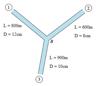
Pressures in each pipe is equal to,
The fluid is water at
The pipe is made of cast iron.
The pressure drop
In the above equation,
The pressure drop in each pipe can be defined as below,
Consider flow in pipe (1) is towards B and the flow in pipe (3) is away from B and the flow in pipe (2) cannot be confirmed.
Calculation:
For pipe 1,
Assume,
Calculate the roughness ratio,
Calculate the Reynolds’s number,
Find the friction factor,
Calculate the pressure at point B,
Calculate the flow rate,
For pipe 2,
Assume,
Calculate the roughness ratio,
Calculate the Reynolds’s number,
Find the friction factor,
Calculate the pressure at point B,
Calculate the flow rate,
For pipe 3,
Assume,
Calculate the roughness ratio,
Calculate the Reynolds’s number,
Find the friction factor,
Calculate the pressure at point B,
Calculate the flow rate,
Calculate the average value of
The friction factor will not differ a lot; we can use the same friction factor to find relevant velocities,
For pipe (1)
The flow rate is equal to,
The flow in pipe (1) is considered as a flow towards junction B.
For pipe (2)
The flow rate is equal to,
The flow in pipe (2) is considered as a flow away from junction B.
For pipe (3)
The flow rate is equal to,
The flow in pipe (3) is considered as a flow away from junction B.
By further iteration, we an get more accurate answers.
Conclusion:
The flow rates in each pipe is equal to,
Want to see more full solutions like this?
Chapter 6 Solutions
Fluid Mechanics


- Design and assemble on the fluidsim (or a draft) the Hydraulic Drive Circuit, with the following characteristics: (a) Sequential operation, pressure, for the advance and return of the cylinders (according to the proper operation for the device) controlled by a directional 4x3 way, closed center; (b) Speed control for the cylinders, according to the load signal; (c) Pressure counterbalance for cylinder A, in order to compensate for the weight of the assembly.arrow_forwardThis is an old exam practice question. The answer is Pmax = 218.8 kN normal stress governs but why?arrow_forwardMoist air initially at T₁ = 140°C, p₁ = 4 bar, and p₁ = 50% is contained in a 2.0-m³ closed, rigid tank. The tank contents are cooled to T₂ 35°C. Step 1 Determine the temperature at which condensation begins, in °C.arrow_forward
- Air at T₁ = 24°C, p₁ = 1 bar, 50% relative humidity enters an insulated chamber operating at steady state with a mass flow rate of 3 kg/min and mixes with a saturated moist air stream entering at T2=7°C, p₂ = 1 bar. A single mixed stream exits at T3-17°C, p3=1 bar. Neglect kinetic and potential energy effectsarrow_forwardHand calculation of cooling loadarrow_forwardAn HEV has a 24kW battery. How many miles can it go on electricity alone at 40 mph on a flat straight road with no headwind? Assume the rolling resistance factor is 0.018 and the Coefficient of Drag (aerodynamic) is 0.29 the frontal area is 2.25m^2 and the vehicle weighs 1618 kg.arrow_forward
- As shown in the figure below, moist air at T₁ = 36°C, 1 bar, and 35% relative humidity enters a heat exchanger operating at steady state with a volumetric flow rate of 10 m³/min and is cooled at constant pressure to 22°C. Ignoring kinetic and potential energy effects, determine: (a) the dew point temperature at the inlet, in °C. (b) the mass flow rate of moist air at the exit, in kg/min. (c) the relative humidity at the exit. (d) the rate of heat transfer from the moist air stream, in kW. (AV)1, T1 P₁ = 1 bar 11 = 35% 120 T₂=22°C P2 = 1 bararrow_forwardThe inside temperature of a wall in a dwelling is 19°C. If the air in the room is at 21°C, what is the maximum relative humidity, in percent, the air can have before condensation occurs on the wall?arrow_forwardThe inside temperature of a wall in a dwelling is 19°C. If the air in the room is at 21°C, what is the maximum relative humidity, in percent, the air can have before condensation occurs on the wall?arrow_forward
- ###arrow_forwardFind the closed loop transfer function and then plot the step response for diFerentvalues of K in MATLAB. Show step response plot for different values of K. Auto Controls Show solution for transform function and provide matlab code (use k(i) for for loop NO COPIED SOLUTIONSarrow_forwardThis is an old practice exam. The answer is Ta-a = 4.615 MPa max = 14.20 MPa Su = 31.24 MPa Sus = 10.15 MPa but why?arrow_forward
 Elements Of ElectromagneticsMechanical EngineeringISBN:9780190698614Author:Sadiku, Matthew N. O.Publisher:Oxford University Press
 Mechanics of Materials (10th Edition)Mechanical EngineeringISBN:9780134319650Author:Russell C. HibbelerPublisher:PEARSON
 Thermodynamics: An Engineering ApproachMechanical EngineeringISBN:9781259822674Author:Yunus A. Cengel Dr., Michael A. BolesPublisher:McGraw-Hill Education
 Control Systems EngineeringMechanical EngineeringISBN:9781118170519Author:Norman S. NisePublisher:WILEY
 Mechanics of Materials (MindTap Course List)Mechanical EngineeringISBN:9781337093347Author:Barry J. Goodno, James M. GerePublisher:Cengage Learning
 Engineering Mechanics: StaticsMechanical EngineeringISBN:9781118807330Author:James L. Meriam, L. G. Kraige, J. N. BoltonPublisher:WILEY