
The steady flow rates in each pipe and the difference in both the results.
Answer to Problem 6.122P
The flow rates found in this part is 5.2 times lower than that of part P6.121. It is because the flow rate is dependent on the cross-sectional area. Therefore, reducing the diameter from 28 to 15 will decrease the amount of flow rate.
Explanation of Solution
Given information:
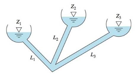
Diameter of all pipes are
At three reservoir junction, if all flows are considered positive towards the junction, then
Assuming the gauge pressure
To solve this type of problems, we should guess the position of
If the
Calculation:
First of all,
Guess
The roughness ratio for all pipes will be,
To find Reynolds’s number,
Therefore,
The friction factor will be equal to,
Therefore, according to the below equation
According to the above result, the Reynolds’s number will be
To find the flow rate,
The flow in pipe 1 is considered as flow away from the junction
Similarly for pipe 2,
To find Reynolds’s number,
 Try
Try
Therefore,
The friction factor will be the same.
According to the above result, the Reynolds’s number will be
To find the flow rate,
The flow in pipe 2 is considered as flow towards the junction.
For pipe 3,
Therefore,
Hence
Try
Therefore,
The friction factor will be the same.
According to the above result, the Reynolds’s number will be
To find the flow rate,
The flow in pipe 1 is considered as flow away from the junction
Similarly for pipe 2,
To find Reynolds’s number,
Therefore,
The friction factor will be same.
According to the above result, the Reynolds’s number will be
To find the flow rate,
The flow in pipe 2 is considered as flow towards the junction.
Similarly for pipe 3,
To find Reynolds’s number,
Try
Therefore,
The friction factor will be equal to,
According to above result, the Reynolds’s number will be
To find the flow rate,
The flow in pipe 3 is considered as flow towards the junction.
Therefore the flow rate will be,
By further iteration, we can get this close to zero, but for now, according to the obtained results, we can say,
In part P6.121, the flow rate were,
Therefore, we can say,
The flow rates found in this part is 5.2 times lower than that of part P6.121. It’s because the flow rate is dependent on the cross-sectional area. Therefore, reducing the diameter from 28 to 15 will decrease the amount of flow rate.
Conclusion:
The flow rates in each pipe is equal to,
The flow rates are 5.2 times lower than that of part P6.121.
Want to see more full solutions like this?
Chapter 6 Solutions
Fluid Mechanics

- For the frame below calculate the bending moment at point R. Take P=40 and note that this value is used for both the loads and the lengths of the members of the frame. 2.5P- A Q B R С 45 degrees ✗ ✗ P i 19 Кур -2P- 4PRN -P- -arrow_forwardCalculate the bending moment at the point D on the beam below. Take F=79 and remember that this quantity is to be used to calculate both forces and lengths. 15F 30F A сarrow_forwardShow work on how to obtain P2 and T2. If using any table, please refer to it. If applying interpolation method, please show the work.arrow_forwardcast-iron roller FIGURE P11-3 Shaft Design for Problems 11-17 Chapter 11 BEARINGS AND LUBRICATION 677 gear key P assume bearings act as simple supports 11-18 Problem 7-18 determined the half-width of the contact patch for a 1.575-in-dia steel cylinder, 9.843 in long, rolled against a flat aluminum plate with 900 lb of force to be 0.0064 in. If the cylinder rolls at 800 rpm, determine its lubrication condition with ISO VG 1000 oil at 200°F. R₁ = 64 μin (cylinder); R₁ = 32 μin (plate). 11-19 The shaft shown in Figure P11-4 was designed in Problem 10-19. For the data in the row(s) assigned from Table P11-1, and the corresponding diameter of shaft found in Problem 10-19, design suitable bearings to support the load for at least 5E8 cycles at 1200 rpm. State all assumptions. (a) (b) Using hydrodynamically lubricated bronze sleeve bearings with ON = 40, 1/ d=0.80, and a clearance ratio of 0.002 5. Using deep-groove ball bearings for a 10% failure rate. *11-20 Problem 7-20 determined the…arrow_forwardCalculate the shear force at the point D on the beam below. Take F=19 and remember that this quantity is to be used to calculate both forces and lengths. 15F A сarrow_forward"II-1 The shaft shown in Figure P11-I was designed in Problem 10-1. For the data in the row(s) assigned from Table P11-1, and the corresponding diameter of shaft found in Problem 10-1, design suitable bearings to support the load for at least 7E7 cycles at 1500 rpm. State all assumptions. (a) Using hydrodynamically lubricated bronze sleeve bearings with Ox = 20, 1/d=1.25, and a clearance ratio of 0.001 5. assume bearings act as simple supports FIGURE P11-1 Shaft Design for Problem 11-1 11-2 The shaft shown in Figure P11-2 was designed in Problem 10-2. For the data in the row(s) assigned from Table P11-1, and the corresponding diameter of shaft found in Problem 10-2, design suitable bearings to support the load for at least 3E8 cycles at 2.500 rpm. State all assumptions. (a) Using hydrodynamically lubricated bronze sleeve bearings with ON=30, 1/d=1.0, and a clearance ratio of 0.002. FIGURE P11-2 Shaft Design for Problem 11-2 Table P11-1 Data for Problems assume bearings act as simple…arrow_forwardFor the frame below, calculate the shear force at point Q. Take P=13 and note that this value is used for both the loads and the lengths of the members of the frame. 1 A Q ✗ 19 KBP 2.5P- B R C 45 degrees ✗ 1 .2P- 4PhN -P→arrow_forwardCalculate the Bending Moment at point D in the frame below. Leave your answer in Nm (newton-metres) J J A 2m 2m <2m х D 不 1m X E 5m 325 Nm 4x 400N/marrow_forwardIn the beam below, calculate the shear force at point A. Take L=78 and remember that both the loads and the dimensions are expressed in terms of L. 143 1 DX A - Li 4 LhN 14LRN/m Х B 22 3 L.arrow_forwardCalculate the Shear Force at Point F on the beam below. Keep your answer in Newtons and make shear force positive to the right. A х 2m <2m E D 5m 1m Хт 325N1m 400N/m 8arrow_forwardThe normal force at C on the beam below is equal to: A ShN C X 15h N 8 ○ OkN 2.5kN 10kN ○ 12.5kN 1m Im 1m 1m;arrow_forwardCalculate the y coordinate of the of the centroid of the shape below. Take A= 18.5 8 6A 4A X 6Aarrow_forwardarrow_back_iosSEE MORE QUESTIONSarrow_forward_iosRecommended textbooks for you
 Elements Of ElectromagneticsMechanical EngineeringISBN:9780190698614Author:Sadiku, Matthew N. O.Publisher:Oxford University Press
 Mechanics of Materials (10th Edition)Mechanical EngineeringISBN:9780134319650Author:Russell C. HibbelerPublisher:PEARSON
 Thermodynamics: An Engineering ApproachMechanical EngineeringISBN:9781259822674Author:Yunus A. Cengel Dr., Michael A. BolesPublisher:McGraw-Hill Education
 Control Systems EngineeringMechanical EngineeringISBN:9781118170519Author:Norman S. NisePublisher:WILEY
 Mechanics of Materials (MindTap Course List)Mechanical EngineeringISBN:9781337093347Author:Barry J. Goodno, James M. GerePublisher:Cengage Learning
 Engineering Mechanics: StaticsMechanical EngineeringISBN:9781118807330Author:James L. Meriam, L. G. Kraige, J. N. BoltonPublisher:WILEY
Elements Of ElectromagneticsMechanical EngineeringISBN:9780190698614Author:Sadiku, Matthew N. O.Publisher:Oxford University PressMechanics of Materials (10th Edition)Mechanical EngineeringISBN:9780134319650Author:Russell C. HibbelerPublisher:PEARSONThermodynamics: An Engineering ApproachMechanical EngineeringISBN:9781259822674Author:Yunus A. Cengel Dr., Michael A. BolesPublisher:McGraw-Hill EducationControl Systems EngineeringMechanical EngineeringISBN:9781118170519Author:Norman S. NisePublisher:WILEYMechanics of Materials (MindTap Course List)Mechanical EngineeringISBN:9781337093347Author:Barry J. Goodno, James M. GerePublisher:Cengage LearningEngineering Mechanics: StaticsMechanical EngineeringISBN:9781118807330Author:James L. Meriam, L. G. Kraige, J. N. BoltonPublisher:WILEY