
Concept explainers
Videos
Design a circuit to amplify the difference between two inputs by 2.5.
- (a) Use only one op amp.
- (b) Use two op amps.
(a)
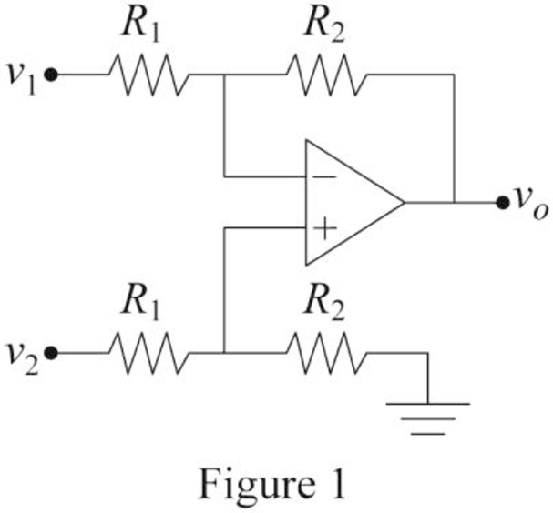
Design an amplifier circuit that contains only one op amp to amplify the required difference between two inputs.
Explanation of Solution
Calculation:
The difference amplifier is drawn and it is shown in Figure 1.
Write the expression for the output voltage
Consider that the required value of difference is 2.5.
Consider the expression for the output voltage of the difference amplifier with the difference of 2.5 between two inputs.
Compare Equations (1) and (2).
Choose the value of resistor
Substitute
Conclusion:
Thus, the required op amp circuit is designed and obtained values are
(b)
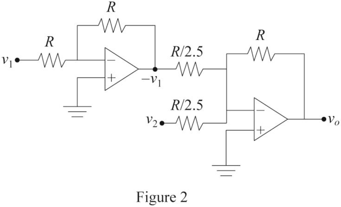
Design an amplifier circuit that contains two op amps to amplify the required difference between two inputs.
Explanation of Solution
Calculation:
Consider that the required value of difference is 2.5. To design the required circuit by cascading the inverting amplifier with summer amplifier.
The required difference amplifier with two op amps is drawn and it is shown in Figure 2.
The output voltage of an inverting amplifier is,
Write the expression for the output voltage
Modify Equation (4).
Hence, Equation (4) satisfies the Equation (2).
Re-arrange Equation (4).
Here,
And
Choose the value of resistor R.
Substitute
Substitute
Substitute
Therefore, the value of resistors
Conclusion:
Thus, the required op amp circuit is designed and obtained values are
Want to see more full solutions like this?
Chapter 5 Solutions
Fundamentals of Electric Circuits


- B) A 60-Hz generator is supply ing 60% of P max to an infinite bus through a reactive network. A fault occurs which increases the reactance of the network between the generator internal voltage and the infinite bus by 400%. When the fault is cleared, the maximum power that can be delivered is 80% of the original maximum value. Determine the critical clearing angle for the condition described.arrow_forwardQ3) A: A generator operating at 50 Hz delivers 1 pu power to an infinite bus through a transmission circuit in which resistance is ignored. A fault takes place reducing the maximum powe transferable to 0.5 pu whereas before the fault, this power was 2.0 pu and after the clearance of the fault, it is 1.5 pu. By the use of equal area criterion, determine the critical clearing angle.arrow_forward4. For the periodic signal shown in Fig. 4; a) Find the exponential Fourier Series for y(t). b) Use Parseval's Theorem to compute the total power contained in the 4th harmonic and all higher harmonics. 2+ y(t) + -2л -л 0 2л Зл 4л Fig. 4arrow_forward
- 2. a) Find the Fourier transform of the signal shown in Fig. 2 and express it in its most compact form; b) Find the value of the energy spectral density at f=1/4. 0 -2 -1 -3. Fig. 1 g(t) 3 1 2 t- Fig 2arrow_forward5. Consider a filter whose transfer function is: H(f) = -12xfß (a + jπ f ) ² (a) show that the filter is non-causal for α = 3, p= -1; (b) choose alternate values of α, ẞ that result in a causal filter, and demonstrate that your choice valid.arrow_forward1. Referring to the signals shown in Fig. 1: a) Find the signal energy of x(t). 6 b) Find the signal energy of y(t) . c) Find the signal energy of x(t)+y(t) . d) Are x(t) and y(t) orthogonal? Explain how you can tell. x(t) 0 2 4 y(1) 2 0 2 4 -6 Fig. 1 1-arrow_forward
- Please can you solve this question correctly in a step by step form to help understanding, please make it clear.arrow_forwardPlease can you solve this question in a step by step form correctly, please look at the refernces provided on the data path control lines, the GPLB functions, the processor instruction setarrow_forwardPlease can you solve this question in a step by step form correctly, please look at the refernces provided on the data path control lines, the GPLB functions, the processor instruction setarrow_forward
- Please can you solve this question in a step by step form correctly, please look at the refernces provided on the data path control lines, the GPLB functions, the processor instruction set and using the PLA personality chart.arrow_forwardPlease can you solve this question correctly in a step by step form to help understanding, please make it clear.arrow_forwardI just want to know what is PPE and Give examples of itarrow_forward
 Introductory Circuit Analysis (13th Edition)Electrical EngineeringISBN:9780133923605Author:Robert L. BoylestadPublisher:PEARSON
 Delmar's Standard Textbook Of ElectricityElectrical EngineeringISBN:9781337900348Author:Stephen L. HermanPublisher:Cengage Learning
 Programmable Logic ControllersElectrical EngineeringISBN:9780073373843Author:Frank D. PetruzellaPublisher:McGraw-Hill Education
 Fundamentals of Electric CircuitsElectrical EngineeringISBN:9780078028229Author:Charles K Alexander, Matthew SadikuPublisher:McGraw-Hill Education
 Electric Circuits. (11th Edition)Electrical EngineeringISBN:9780134746968Author:James W. Nilsson, Susan RiedelPublisher:PEARSON
 Engineering ElectromagneticsElectrical EngineeringISBN:9780078028151Author:Hayt, William H. (william Hart), Jr, BUCK, John A.Publisher:Mcgraw-hill Education,