
Concept explainers
Videos
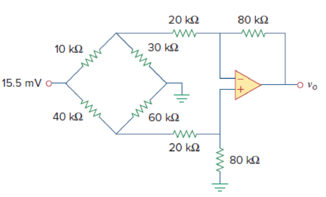
The circuit in Fig. 5.80 is a differential amplifier driven by a bridge. Find vo.
Calculate the output voltage
Answer to Problem 48P
The output voltage
Explanation of Solution
Given data:
Refer Figure 5.80 in the textbook for the differential amplifier that is driven by a bridge circuit.
Calculation:
Consider break this problem up into parts. The 15.5 mV voltage source splits the lower circuit from the upper circuit. In addition, there is no current flowing into the op amp input which means we now have the
Consider the expression for the current flows through the circuit.
Substitute 15.5 mV for
The voltage across the
Substitute
The voltage across the
This voltage is also the voltage at both inputs of the op amp and the voltage between the
Modify Figure 5.80 by indicating the node voltages. The modified figure as shown in Figure 1.
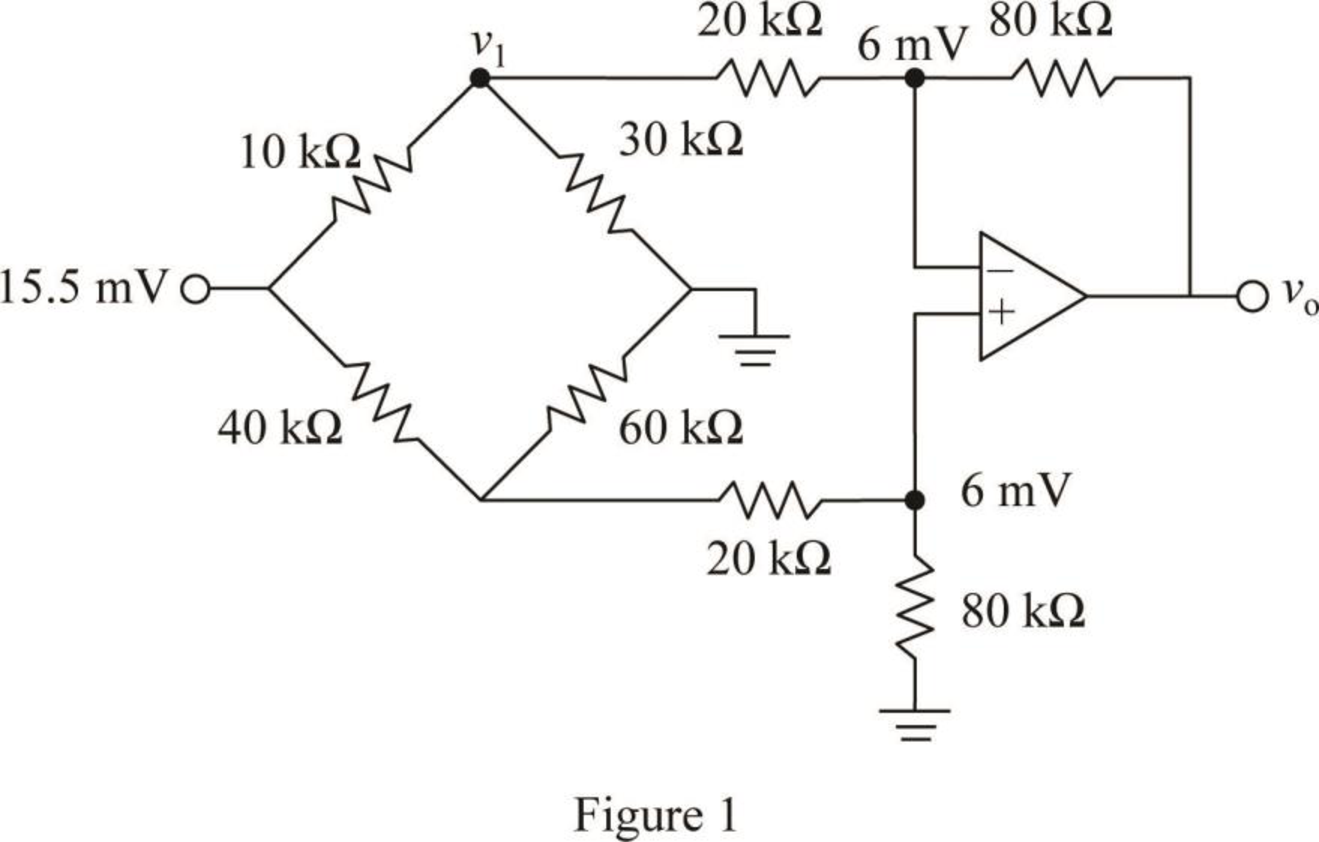
Write a node equation at node
Consider the expression for the current through the
Substitute 10.091 mV for
Write the expression for the output voltage
Substitute
Conclusion:
Thus, the output voltage
Want to see more full solutions like this?
Chapter 5 Solutions
Fundamentals of Electric Circuits


- Please solve it by explaining the steps. I am trying to prepare for my exam tomorrow, so any tips and tricks to solve similar problems are highly appreciated. Plus, this is a past exam I am using to prepare.arrow_forwardPlease solve it by explaining the steps. I am trying to prepare for my exam tomorrow, so any tips and tricks to solve similar problems are highly appreciated. Plus, this is a past exam I am using to prepare.arrow_forwardPlease solve it by explaining the steps. I am trying to prepare for my exam tomorrow, so any tips and tricks to solve similar problems are highly appreciated. Plus, this is a past exam I am using to prepare.arrow_forward
- Please solve it by explaining the steps. I am trying to prepare for my exam tomorrow, so any tips and tricks to solve similar problems are highly appreciated. Plus, this is a past exam I am using to prepare.arrow_forwardPlease solve it by explaining the steps. I am trying to prepare for my exam tomorrow, so any tips and tricks to solve similar problems are highly appreciated. Plus, this is a past exam I am using to prepare.arrow_forwardPlease solve it by explaining the steps. I am trying to prepare for my exam tomorrow, so any tips and tricks to solve similar problems are highly appreciated. Plus, this is a past exam I am using to prepare.arrow_forward
- It is a past exam for practice, please explain what you do so I can be prepared for exam tomorrowarrow_forwardPlease solve it by explaining the steps. I am trying to prepare for my exam tomorrow, so any tips and tricks to solve similar problems are highly appreciated. Plus, this is a past exam I am using to prepare.arrow_forwardPlease solve it by explaining the steps. I am trying to prepare for my exam tomorrow, so any tips and tricks to solve similar problems are highly appreciated. Plus, this is a past exam I am using to prepare.arrow_forward
- Please solve it by explaining the steps. I am trying to prepare for my exam tomorrow, so any tips and tricks to solve similar problems are highly appreciated. Plus, this is a past exam I am using to prepare.arrow_forwardIf C is the circle |z|=4 evaluate ff(z)dz for each of the following functions using residue. Z (a)f(z) = z²-1 Z+1 1 (b)f(z) = = (c)f(z) = z²(z+2) z(z-2)³ z² 1 1 (d) f(z) = = (e) f(z) = (f) f(z) = (z²+3z+2)² z²+z+1 z(z²+6z+4)arrow_forward5. Answer the following questions. Take help from ChatGPT to answer these questions (if you need). Write the answers briefly using your own words with no more than two sentences, and check whether ChatGPT is giving you the appropriate answers in the context of our class. a) What is the Bode plot? What kind of input do we consider for the frequency-response- based method? b) What is the advantage of design using the frequency-response method? c) Define gain margin, phase margin, gain crossover frequency, and phase crossover frequency.arrow_forward
 Delmar's Standard Textbook Of ElectricityElectrical EngineeringISBN:9781337900348Author:Stephen L. HermanPublisher:Cengage Learning