
EBK MECHANICS OF MATERIALS
7th Edition
ISBN: 9780100257061
Author: BEER
Publisher: YUZU
expand_more
expand_more
format_list_bulleted
Videos
Textbook Question
Chapter 4.3, Problem 8P
4.7 and 4.8 Two W4 × 13 rolled sections are welded together as shown. Knowing that for the steel alloy used σU = 58 ksi and using a factor of safety of 3.0, determine the largest couple that can be applied when the assembly is bent about the z axis.
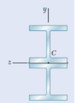
Fig.P4.8
Expert Solution & Answer

Trending nowThis is a popular solution!

Students have asked these similar questions
Please can you help with ten attatched question?
An AISI 1018 steel ball with 1.100-in diameter is used as a roller between a flat plate
made from 2024 T3 aluminum and a flat table surface made from ASTM No. 30 gray
cast iron. Determine the maximum amount of weight that can be stacked on the
aluminum plate without exceeding a maximum shear stress of 19.00 kpsi in any of the
three pieces. Assume the figure given below, which is based on a typical Poisson's
ratio of 0.3, is applicable to estimate the depth at which the maximum shear stress
occurs for these materials.
1.0
0.8
Ratio of stress to Pmax
0.4
90
0.6
στ
Tmax
0.2
0.5a
a
1.5a
2a
2.5a
За
Distance from contact surface
The maximum amount of weight that can be stacked on the aluminum plate is
lbf.
A carbon steel ball with 27.00-mm diameter is pressed together with an aluminum ball
with a 36.00-mm diameter by a force of 11.00 N. Determine the maximum shear
stress and the depth at which it will occur for the aluminum ball. Assume the figure
given below, which is based on a typical Poisson's ratio of 0.3, is applicable to estimate
the depth at which the maximum shear stress occurs for these materials.
1.0
0.8
Ratio of stress to Pma
9 0.6
στ
24
0.4
Tmax
0.2
0
0.5a
a
1.5a
Z
2a
2.5a
За
Distance from contact surface
The maximum shear stress is determined to be
MPa.
The depth in the aluminum ball at which the maximum shear stress will occur is
determined to be [
mm.
Chapter 4 Solutions
EBK MECHANICS OF MATERIALS
Ch. 4.3 - 4.1 and 4.2 Knowing that the couple shown acts in...Ch. 4.3 - 4.1 and 4.2 Knowing that the couple shown acts in...Ch. 4.3 - Using an allowable stress of 155 MPa, determine...Ch. 4.3 - Solve Prob. 4.3, assuming that the wide-flange...Ch. 4.3 - Using an allowable stress of 16 ksi, determine the...Ch. 4.3 - Knowing that the couple shown acts in a vertical...Ch. 4.3 - 4.7 and 4.8 Two W4 13 rolled sections are welded...Ch. 4.3 - 4.7 and 4.8 Two W4 13 rolled sections are welded...Ch. 4.3 - 4.9 through 4.11 Two vertical forces are applied...Ch. 4.3 - 4.9 through 4.11 Two vertical forces are applied...
Ch. 4.3 - 4.9 through 4.11 Two vertical forces are applied...Ch. 4.3 - Knowing that a beam of the cross section shown is...Ch. 4.3 - Knowing that a beam of the cross section shown is...Ch. 4.3 - Solve Prob. 4.13, assuming that the beam is bent...Ch. 4.3 - Knowing that for the extruded beam shown the...Ch. 4.3 - The beam shown is made of a nylon for which the...Ch. 4.3 - Solve Prob. 4.16, assuming that d = 40 mm.Ch. 4.3 - Knowing that for the beam shown the allowable...Ch. 4.3 - 4.19 and 4.20 Knowing that for the extruded beam...Ch. 4.3 - 4.19 and 4.20 Knowing that for the extruded beam...Ch. 4.3 - Straight rods of 6-mm diameter and 30-m length are...Ch. 4.3 - A 900-mm strip of steel is bent into a full circle...Ch. 4.3 - Straight rods of 0.30-in. diameter and 200-ft...Ch. 4.3 - A 60-Nm couple is applied to the steel bar shown,...Ch. 4.3 - (a) Using an allowable stress of 120 MPa,...Ch. 4.3 - A thick-walled pipe is bent about a horizontal...Ch. 4.3 - A couple M will be applied to a beam of...Ch. 4.3 - A portion of a square bar is removed by milling,...Ch. 4.3 - In Prob. 4.28, determine (a) the value of h for...Ch. 4.3 - For the bar and loading of Concept Application...Ch. 4.3 - Prob. 31PCh. 4.3 - It was assumed in Sec. 4.1B that the normal...Ch. 4.5 - 4.33 and 4.34 A bar having the cross section shown...Ch. 4.5 - 4.33 and 4.34 A bar having the cross section shown...Ch. 4.5 - 4.35 and 4.36 For the composite bar indicated,...Ch. 4.5 - Prob. 36PCh. 4.5 - 4.37 and 4.38 Wooden beams and steel plates are...Ch. 4.5 - 4.37 and 4.38 Wooden beams and steel plates are...Ch. 4.5 - 4.39 and 4.40 A copper strip (Ec = 105 GPa) and an...Ch. 4.5 - 4.39 and 4.40 A copper strip (Ec = 105 GPa) and an...Ch. 4.5 - 4.41 and 4.42 The 6 12-in. timber beam has been...Ch. 4.5 - 4.41 and 4.42 The 6 12-in. timber beam has been...Ch. 4.5 - 4.43 and 4.44 For the composite beam indicated,...Ch. 4.5 - Prob. 44PCh. 4.5 - Prob. 45PCh. 4.5 - Prob. 46PCh. 4.5 - A concrete slab is reinforced by 58-in.-diameter...Ch. 4.5 - Solve Prob. 4.47, assuming that the spacing of the...Ch. 4.5 - The reinforced concrete beam shown is subjected to...Ch. 4.5 - Prob. 50PCh. 4.5 - Knowing that the bending moment in the reinforced...Ch. 4.5 - A concrete beam is reinforced by three steel rods...Ch. 4.5 - The design of a reinforced concrete beam is said...Ch. 4.5 - For the concrete beam shown, the modulus of...Ch. 4.5 - 4.55 and 4.56 Five metal strips, each 0.5 1.5-in....Ch. 4.5 - 4.55 and 4.56 Five metal strips, each 0.5 1.5-in....Ch. 4.5 - The composite beam shown is formed by bonding...Ch. 4.5 - A steel pipe and an aluminum pipe are securely...Ch. 4.5 - The rectangular beam shown is made of a plastic...Ch. 4.5 - Prob. 60PCh. 4.5 - Knowing that M = 250 Nm, determine the maximum...Ch. 4.5 - Knowing that the allowable stress for the beam...Ch. 4.5 - Semicircular grooves of radius r must be milled as...Ch. 4.5 - Prob. 64PCh. 4.5 - A couple of moment M = 2 kNm is to be applied to...Ch. 4.5 - The allowable stress used in the design of a steel...Ch. 4.6 - The prismatic bar shown is made of a steel that is...Ch. 4.6 - Prob. 68PCh. 4.6 - Prob. 69PCh. 4.6 - Prob. 70PCh. 4.6 - The prismatic rod shown is made of a steel that is...Ch. 4.6 - Solve Prob. 4.71, assuming that the couples M and...Ch. 4.6 - 4.73 and 4.74 A beam of the cross section shown is...Ch. 4.6 - 4.73 and 4.74 A beam of the cross section shown is...Ch. 4.6 - 4.75 and 4.76 A beam of the cross section shown is...Ch. 4.6 - Prob. 76PCh. 4.6 - 4.77 through 4.80 For the beam indicated,...Ch. 4.6 - Prob. 78PCh. 4.6 - Prob. 79PCh. 4.6 - 4.77 through 4.80 For the beam indicated,...Ch. 4.6 - 4.81 through 4.83 Determine the plastic moment Mp...Ch. 4.6 - Prob. 82PCh. 4.6 - Prob. 83PCh. 4.6 - Determine the plastic moment Mp of a steel beam of...Ch. 4.6 - Determine the plastic moment Mp of the cross...Ch. 4.6 - Determine the plastic moment Mp of a steel beam of...Ch. 4.6 - Prob. 87PCh. 4.6 - Prob. 88PCh. 4.6 - Prob. 89PCh. 4.6 - Prob. 90PCh. 4.6 - Prob. 91PCh. 4.6 - Prob. 92PCh. 4.6 - Prob. 93PCh. 4.6 - Prob. 94PCh. 4.6 - Prob. 95PCh. 4.6 - Prob. 96PCh. 4.6 - Prob. 97PCh. 4.6 - Prob. 98PCh. 4.7 - Knowing that the magnitude of the horizontal force...Ch. 4.7 - A short wooden post supports a 6-kip axial load as...Ch. 4.7 - Two forces P can be applied separately or at the...Ch. 4.7 - A short 120 180-mm column supports the three...Ch. 4.7 - As many as three axial loads, each of magnitude P...Ch. 4.7 - Two 10-kN forces are applied to a 20 60-mm...Ch. 4.7 - Portions of a 1212-in. square bar have been bent...Ch. 4.7 - Knowing that the allowable stress in section ABD...Ch. 4.7 - A milling operation was used to remove a portion...Ch. 4.7 - A milling operation was used to remove a portion...Ch. 4.7 - The two forces shown are applied to a rigid plate...Ch. 4.7 - Prob. 110PCh. 4.7 - Prob. 111PCh. 4.7 - A short column is made by nailing four 1 4-in....Ch. 4.7 - A vertical rod is attached at point A to the cast...Ch. 4.7 - A vertical rod is attached at point A to the cast...Ch. 4.7 - Knowing that the clamp shown has been tightened...Ch. 4.7 - Prob. 116PCh. 4.7 - Three steel plates, each of 25 150-mm cross...Ch. 4.7 - A vertical force P of magnitude 20 kips is applied...Ch. 4.7 - The four bars shown have the same cross-sectional...Ch. 4.7 - Prob. 120PCh. 4.7 - An eccentric force P is applied as shown to a...Ch. 4.7 - Prob. 122PCh. 4.7 - Prob. 123PCh. 4.7 - Prob. 124PCh. 4.7 - A single vertical force P is applied to a short...Ch. 4.7 - The eccentric axial force P acts at point D, which...Ch. 4.9 - 4.127 through 4.134 The couple M is applied to a...Ch. 4.9 - 4.127 through 4.134 The couple M is applied to a...Ch. 4.9 - 4.127 through 4.134 The couple M is applied to a...Ch. 4.9 - 4.127 through 4.134 The couple M is applied to a...Ch. 4.9 - 4.127 through 4.134 The couple M is applied to a...Ch. 4.9 - 4.127 through 4.134 The couple M is applied to a...Ch. 4.9 - Prob. 133PCh. 4.9 - Prob. 134PCh. 4.9 - 4.135 through 4.140 The couple M acts in a...Ch. 4.9 - 4.135 through 4.140 The couple M acts in a...Ch. 4.9 - Prob. 137PCh. 4.9 - 4.135 through 4.140 The couple M acts in a...Ch. 4.9 - 4.135 through 44.140 The couple M acts in a...Ch. 4.9 - 4.135 through 4.140 The couple M acts in a...Ch. 4.9 - Prob. 141PCh. 4.9 - 4.141 through 4.143 The couple M acts in a...Ch. 4.9 - 4.141 through 4.143 The couple M acts in a...Ch. 4.9 - The tube shown has a uniform wall thickness of 12...Ch. 4.9 - Prob. 145PCh. 4.9 - Knowing that P = 90 kips, determine the largest...Ch. 4.9 - Knowing that a = 1.25 in., determine the largest...Ch. 4.9 - A rigid circular plate of 125-mm radius is...Ch. 4.9 - Prob. 149PCh. 4.9 - A beam having the cross section shown is subjected...Ch. 4.9 - Prob. 151PCh. 4.9 - Prob. 152PCh. 4.9 - Prob. 153PCh. 4.9 - Prob. 154PCh. 4.9 - Prob. 155PCh. 4.9 - Prob. 156PCh. 4.9 - Prob. 157PCh. 4.9 - Prob. 158PCh. 4.9 - A beam of unsymmetric cross section is subjected...Ch. 4.9 - Prob. 160PCh. 4.10 - For the curved bar shown, determine the stress at...Ch. 4.10 - For the curved bar shown, determine the stress at...Ch. 4.10 - Prob. 163PCh. 4.10 - Prob. 164PCh. 4.10 - The curved bar shown has a cross section of 40 60...Ch. 4.10 - Prob. 166PCh. 4.10 - Prob. 167PCh. 4.10 - Prob. 168PCh. 4.10 - The curved bar shown has a cross section of 30 30...Ch. 4.10 - Prob. 170PCh. 4.10 - Prob. 171PCh. 4.10 - Three plates are welded together to form the...Ch. 4.10 - 4.173 and 4.174 Knowing that the maximum allowable...Ch. 4.10 - Prob. 174PCh. 4.10 - Prob. 175PCh. 4.10 - Prob. 176PCh. 4.10 - Prob. 177PCh. 4.10 - Prob. 178PCh. 4.10 - Prob. 179PCh. 4.10 - Knowing that P = 10 kN, determine the stress at...Ch. 4.10 - Prob. 181PCh. 4.10 - Prob. 182PCh. 4.10 - Prob. 183PCh. 4.10 - Prob. 184PCh. 4.10 - Prob. 185PCh. 4.10 - Prob. 186PCh. 4.10 - Prob. 187PCh. 4.10 - Prob. 188PCh. 4.10 - Prob. 189PCh. 4.10 - Prob. 190PCh. 4.10 - For a curved bar of rectagular cross section...Ch. 4 - Two vertical forces are applied to a beam of the...Ch. 4 - Prob. 193RPCh. 4 - Prob. 194RPCh. 4 - Determine the plastic moment Mp of a steel beam of...Ch. 4 - In order to increase corrosion resistance, a...Ch. 4 - The vertical portion of the press shown consists...Ch. 4 - The four forces shown are applied to a rigid plate...Ch. 4 - Prob. 199RPCh. 4 - Prob. 200RPCh. 4 - Three 120 10-mm steel plates have been welded...Ch. 4 - A short length of a W8 31 rolled-steel shape...Ch. 4 - Two thin strips of the same material and same...
Additional Engineering Textbook Solutions
Find more solutions based on key concepts
What types of coolant are used in vehicles?
Automotive Technology: Principles, Diagnosis, And Service (6th Edition) (halderman Automotive Series)
This optional Google account security feature sends you a message with a code that you must enter, in addition ...
SURVEY OF OPERATING SYSTEMS
The job of the _____ is to fetch instructions, carry out the operations commanded by the instructions, and prod...
Starting Out With Visual Basic (8th Edition)
The solid steel shaft AC has a diameter of 25 mm and is supported by smooth bearings at D and E. It is coupled ...
Mechanics of Materials (10th Edition)
Assume a telephone signal travels through a cable at two-thirds the speed of light. How long does it take the s...
Electric Circuits. (11th Edition)
17–1C A high-speed aircraft is cruising in still air. How does the temperature of air at the nose of the aircra...
Thermodynamics: An Engineering Approach
Knowledge Booster


Learn more about
Need a deep-dive on the concept behind this application? Look no further. Learn more about this topic, mechanical-engineering and related others by exploring similar questions and additional content below.Similar questions
- Show all work pleasearrow_forwardDraw top, side, front view With pen(cil) and paper Multi view drawing and handwriting all of itarrow_forwardA wheel of diameter 150.0 mm and width 37.00 mm carrying a load 2.200 kN rolls on a flat rail. Take the wheel material as steel and the rail material as cast iron. Assume the figure given, which is based on a Poisson's ratio of 0.3, is applicable to estimate the depth at which the maximum shear stress occurs for these materials. At this critical depth, calculate the Hertzian stresses σr, σy, σz, and Tmax for the wheel. 1.0 0.8 0, т Ratio of stress to Pmax 0.4 0.6 90 69 0.2 0.5b b 1.5b Tmax 2b Distance from contact surface The Hertizian stresses are as follows: 02 = or = -23.8 psi for the wheel =| necessary.) σy for the wheel =| MPa σz for the wheel = MPa V4 for the wheel = | MPa 2.5b ཡི 3b MPa (Include a minus sign ifarrow_forward
- 4. Solve for the support reactions at A and B. W1 600 lb/ft W2 150 lb/ft A Barrow_forwardIn cold isostatic pressing, the mold is most typically made of which one of the following: thermosetting polymer tool steel sheet metal textile rubberarrow_forwardThe coefficient of friction between the part and the tool in cold working tends to be: lower higher no different relative to its value in hot workingarrow_forward
- The force F={25i−45j+15k}F={25i−45j+15k} lblb acts at the end A of the pipe assembly shown in (Figure 1). Determine the magnitude of the component F1 which acts along the member AB. Determine the magnitude of the component F2 which acts perpendicular to the AB.arrow_forwardHi can you please help me with the attached question?arrow_forwardHi can you please help me with the attached question?arrow_forward
arrow_back_ios
SEE MORE QUESTIONS
arrow_forward_ios
Recommended textbooks for you
 Elements Of ElectromagneticsMechanical EngineeringISBN:9780190698614Author:Sadiku, Matthew N. O.Publisher:Oxford University Press
 Mechanics of Materials (10th Edition)Mechanical EngineeringISBN:9780134319650Author:Russell C. HibbelerPublisher:PEARSON
 Thermodynamics: An Engineering ApproachMechanical EngineeringISBN:9781259822674Author:Yunus A. Cengel Dr., Michael A. BolesPublisher:McGraw-Hill Education
 Control Systems EngineeringMechanical EngineeringISBN:9781118170519Author:Norman S. NisePublisher:WILEY
 Mechanics of Materials (MindTap Course List)Mechanical EngineeringISBN:9781337093347Author:Barry J. Goodno, James M. GerePublisher:Cengage Learning
 Engineering Mechanics: StaticsMechanical EngineeringISBN:9781118807330Author:James L. Meriam, L. G. Kraige, J. N. BoltonPublisher:WILEY
Elements Of Electromagnetics
Mechanical Engineering
ISBN:9780190698614
Author:Sadiku, Matthew N. O.
Publisher:Oxford University Press
Mechanics of Materials (10th Edition)
Mechanical Engineering
ISBN:9780134319650
Author:Russell C. Hibbeler
Publisher:PEARSON
Thermodynamics: An Engineering Approach
Mechanical Engineering
ISBN:9781259822674
Author:Yunus A. Cengel Dr., Michael A. Boles
Publisher:McGraw-Hill Education
Control Systems Engineering
Mechanical Engineering
ISBN:9781118170519
Author:Norman S. Nise
Publisher:WILEY
Mechanics of Materials (MindTap Course List)
Mechanical Engineering
ISBN:9781337093347
Author:Barry J. Goodno, James M. Gere
Publisher:Cengage Learning
Engineering Mechanics: Statics
Mechanical Engineering
ISBN:9781118807330
Author:James L. Meriam, L. G. Kraige, J. N. Bolton
Publisher:WILEY
Differences between Temporary Joining and Permanent Joining.; Author: Academic Gain Tutorials;https://www.youtube.com/watch?v=PTr8QZhgXyg;License: Standard Youtube License