
Concept explainers
Videos
a)
Show that the maximum compressive stresses are in the ratio 4:5:7:9.
a)
Explanation of Solution
Given information:
The load act on the point of the bars is P.
Calculation:
At the point A:
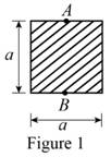
Show the cross-sectional diagram of the square bar as in Figure 1.
Here,
Refer to Figure 1.
The maximum compressive stress of the square bar
Here, e is the eccentricity of the load and
The cross-sectional area of the square bar
The eccentricity of the load (e) is
The distance between the centroid from extreme fibre
The moment of inertia
Calculate the maximum compressive stress of the square bar
Substitute
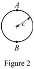
Show the cross-sectional diagram of the circular bar as in Figure 2.
Here,
Refer to Figure 2.
The maximum compressive stress of the circular bar
The cross-sectional area of the circular bar
The eccentricity of the load (e) is
The distance between the centroid from extreme fibre
The moment of inertia
Calculate the maximum compressive stress of the circular bar
Substitute
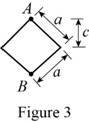
Show the cross-sectional diagram of the diamond shape bar as in Figure 3.
Here,
Refer to Figure 3.
The maximum compressive stress of the diamond shape bar
The cross-sectional area of the diamond shape bar
The eccentricity of the load (e) is
The distance between the centroid from extreme fibre
The moment of inertia
Calculate the maximum compressive stress of the diamond shape bar
Substitute
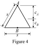
Show the cross-sectional diagram of the triangular bar as in Figure 4.
Here,
Refer to Figure 4.
The maximum compressive stress of the triangular bar
The cross-sectional area of the triangular bar
The distance between the centroid from extreme fibre
The eccentricity of the load (e) is
The moment of inertia
Calculate the maximum compressive stress of the triangular bar
Substitute
Calculate the maximum compressive stresses are in the ratio:
Substitute
The four bars shown have the same cross-sectional area.
Hence the maximum compressive stresses are in the ratio 4:5:7:9 is proved.
b)
Show that the maximum tensile stresses are in the ratio 2:3:5:3.
b)
Explanation of Solution
Given information:
The load act on the point of the bars is P.
Calculation:
At the point B:
Refer to Figure 1.
The maximum tensile stress of the square bar
Here, the e is the eccentricity of the load and
The cross-sectional area of the square bar
The eccentricity of the load (e) is
The distance between the centroid from extreme fibre
The moment of inertia
Calculate the maximum tensile stress of the square bar
Substitute
Refer to Figure 2.
The maximum tensile stress of the circular bar
The cross-sectional area of the circular bar
The eccentricity of the load (e) is
The distance between the centroid from extreme fibre
The moment of inertia
Calculate the maximum tensile stress of the circular bar
Substitute
Refer to Figure 3.
The maximum tensile stress of the diamond shape bar
The cross-sectional area of the diamond shape bar
The eccentricity of the load (e) is
The distance between the centroid from extreme fibre
The moment of inertia
Calculate the maximum tensile stress of the diamond shape bar
Substitute
Refer to Figure 4.
The maximum tensile stress of the triangular bar
The cross-sectional area of the triangular bar
The distance between the centroid from extreme fibre
The eccentricity of the load (e) is
The moment of inertia
Calculate the maximum tensile stress of the triangular bar
Substitute
Calculate the maximum tensile stresses are in the ratio:
Substitute
The four bars shown have the same cross-sectional area.
Hence the maximum tensile stresses are in the ratio 2:3:5:3 is proved.
Want to see more full solutions like this?
Chapter 4 Solutions
EBK MECHANICS OF MATERIALS


- 11-5. Compute all the dimensional changes for the steel bar when subjected to the loads shown. The proportional limit of the steel is 230 MPa. 265 kN 100 mm 600 kN 25 mm thickness X Z 600 kN 450 mm E=207×103 MPa; μ= 0.25 265 kNarrow_forwardT₁ F Rd = 0.2 m md = 2 kg T₂ Tz1 Rc = 0.4 m mc = 5 kg m = 3 kgarrow_forward2. Find a basis of solutions by the Frobenius method. Try to identify the series as expansions of known functions. (x + 2)²y" + (x + 2)y' - y = 0 ; Hint: Let: z = x+2arrow_forward
- 1. Find a power series solution in powers of x. y" - y' + x²y = 0arrow_forward3. Find a basis of solutions by the Frobenius method. Try to identify the series as expansions of known functions. 8x2y" +10xy' + (x 1)y = 0 -arrow_forwardHello I was going over the solution for this probem and I'm a bit confused on the last part. Can you please explain to me 1^4 was used for the Co of the tubular cross section? Thank you!arrow_forward
- Blood (HD = 0.45 in large diameter tubes) is forced through hollow fiber tubes that are 20 µm in diameter.Equating the volumetric flowrate expressions from (1) assuming marginal zone theory and (2) using an apparentviscosity for the blood, estimate the marginal zone thickness at this diameter. The viscosity of plasma is 1.2 cParrow_forwardQ2: Find the shear load on bolt A for the connection shown in Figure 2. Dimensions are in mm Fig. 2 24 0-0 0-0 A 180kN (10 Markarrow_forwarddetermine the direction and magnitude of angular velocity ω3 of link CD in the four-bar linkage using the relative velocity graphical methodarrow_forward
- Four-bar linkage mechanism, AB=40mm, BC=60mm, CD=70mm, AD=80mm, =60°, w1=10rad/s. Determine the direction and magnitude of w3 using relative motion graphical method. A B 2 3 77777 477777arrow_forwardFour-bar linkage mechanism, AB=40mm, BC=60mm, CD=70mm, AD=80mm, =60°, w1=10rad/s. Determine the direction and magnitude of w3 using relative motion graphical method. A B 2 3 77777 477777arrow_forwardThe evaporator of a vapor compression refrigeration cycle utilizing R-123 as the refrigerant isbeing used to chill water. The evaporator is a shell and tube heat exchanger with the water flowingthrough the tubes. The water enters the heat exchanger at a temperature of 54°F. The approachtemperature difference of the evaporator is 3°R. The evaporating pressure of the refrigeration cycleis 4.8 psia and the condensing pressure is 75 psia. The refrigerant is flowing through the cycle witha flow rate of 18,000 lbm/hr. The R-123 leaves the evaporator as a saturated vapor and leaves thecondenser as a saturated liquid. Determine the following:a. The outlet temperature of the chilled waterb. The volumetric flow rate of the chilled water (gpm)c. The UA product of the evaporator (Btu/h-°F)d. The heat transfer rate between the refrigerant and the water (tons)arrow_forward
 International Edition---engineering Mechanics: St...Mechanical EngineeringISBN:9781305501607Author:Andrew Pytel And Jaan KiusalaasPublisher:CENGAGE L