
Concept explainers
Videos
A rigid circular plate of 125-mm radius is attached to a solid 150 × 200-mm rectangular post, with the center of the plate directly above the center of the post. If a 4-kN force P is applied at E with θ = 30°, determine (a) the stress at point A, (b) the stress at point B, (c) the point where the neutral axis intersects line ABD.
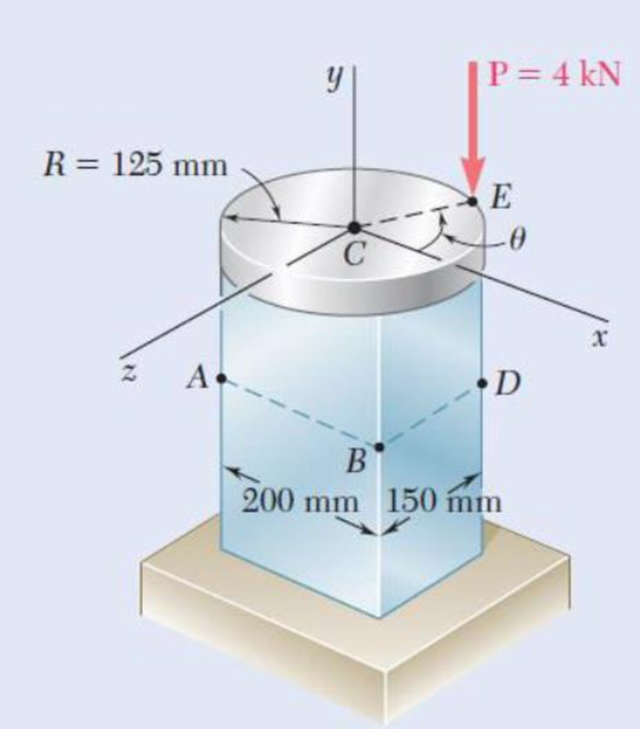
Fig. P4.148
(a)
Find the value of stress at point A.
Answer to Problem 148P
The stress at point A is
Explanation of Solution
Given information:
The radius of the circular plate is
The width of the rectangular post is
The applied force is
Calculation:
Sketch the cross section of disk as shown in Figure 1.
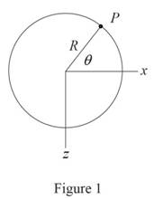
Refer to Figure 1.
Consider the value of angle
Calculate the moment along
Substitute
Calculate the moment along
Substitute
Sketch the cross section of the rectangular post as shown in Figure 2.
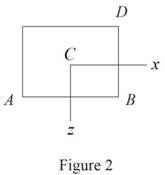
Refer to Figure 2.
Calculate the area
Substitute
Calculate the moment of inertia along
Substitute
Calculate the moment of inertia along
Substitute
Calculate the stress
Refer to Figure 2.
The location of point A along
The location of point A along
Calculate the stress at A
Substitute
Hence, the stress at A is
(b)
The values of stress at B.
Answer to Problem 148P
The stress at B is
Explanation of Solution
Given information:
Calculation:
Calculate the stress at B
Refer to Figure 2 in part (a).
The location of point B along
The location of point B along
Substitute
Hence, the stress at B is
(c)
The point where the neutral axis intersect ABD.
Answer to Problem 148P
The point where the neutral axis intersect ABD is
Explanation of Solution
Given information:
Calculation:
The stress at G
Refer to Figure 2 in part (a).
The location of point G along
The location of point G along
Substitute
Show the distance (d) between the point A and the point G as follows:
Thus, The point where the neutral axis intersect ABD is
Want to see more full solutions like this?
Chapter 4 Solutions
EBK MECHANICS OF MATERIALS


- My ID#016948724 please solve this problems and show me every step clear to follow pleasearrow_forwardMy ID# 016948724arrow_forwardPlease do not use any AI tools to solve this question. I need a fully manual, step-by-step solution with clear explanations, as if it were done by a human tutor. No AI-generated responses, please.arrow_forward
- Please do not use any AI tools to solve this question. I need a fully manual, step-by-step solution with clear explanations, as if it were done by a human tutor. No AI-generated responses, please.arrow_forwardPlease do not use any AI tools to solve this question. I need a fully manual, step-by-step solution with clear explanations, as if it were done by a human tutor. No AI-generated responses, please.arrow_forward[Q2]: The cost information supplied by the cost accountant is as follows:Sales 20,00 units, $ 10 per unitCalculate the (a/ newsale guantity and (b) new selling price to earn the sameVariable cost $ 6 per unit, Fixed Cost $ 30,000, Profit $ 50,000profit ifi) Variable cost increases by $ 2 per unitil) Fixed cost increase by $ 10,000Ili) Variable cost increase by $ 1 per unit and fixed cost reduces by $ 10,000arrow_forward
- can you please help me perform Visual Inspection and Fractography of the attatched image: Preliminary examination to identify the fracture origin, suspected fatigue striation, and corrosion evidences.arrow_forwardcan you please help[ me conduct Causal Analysis (FTA) on the scenario attatched: FTA diagram which is a fault tree analysis diagram will be used to gain an overview of the entire path of failure from root cause to the top event (i.e., the swing’s detachment) and to identify interactions between misuse, material decay and inspection errors.arrow_forwardhi can you please help me in finding the stress intensity factor using a k-calcluator for the scenario attathced in the images.arrow_forward
 International Edition---engineering Mechanics: St...Mechanical EngineeringISBN:9781305501607Author:Andrew Pytel And Jaan KiusalaasPublisher:CENGAGE L
 Mechanics of Materials (MindTap Course List)Mechanical EngineeringISBN:9781337093347Author:Barry J. Goodno, James M. GerePublisher:Cengage Learning