
EBK MECHANICS OF MATERIALS
7th Edition
ISBN: 9780100257061
Author: BEER
Publisher: YUZU
expand_more
expand_more
format_list_bulleted
Concept explainers
Videos
Textbook Question
Chapter 4.9, Problem 146P
Knowing that P = 90 kips, determine the largest distance a for which the maximum compressive stress does not exceed 18 ksi.
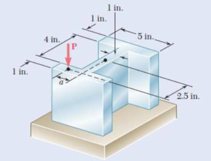
Fig. P4.146 and P4.147
Expert Solution & Answer

Trending nowThis is a popular solution!

Students have asked these similar questions
2.64
A 2.75-kN tensile load is applied to a test coupon made from 1.6-mm flat steel plate (E = 200 GPa, v = 0.30).
Determine the resulting change in (a) the 50-mm gage length, (b) the width of portion AB of the test coupon,
(c) the thickness of portion AB, (d) the cross-sectional area of portion AB.
2.75 kN
A
12 mm
50 mm
B
2.75 kN
Procedure:1- Cartesian system, 2(D)/(3)D,type of support2- Free body diagram3 - Find the support reactions4- If you find a negativenumber then flip the force5- Find the internal force3D\sum Fx=0\sum Fy=0\sum Fz=0\sum Mx=0\sum My=0\Sigma Mz=02D\Sigma Fx=0\Sigma Fy=0\Sigma Mz=05- Use method of sectionand cut the elementwhere you want to findthe internal force andkeep either side of thesection
3. The design of a pump and pipe system has been completed, except for the valves. The system
is used to transpor10t water at 120°F through 2 nom sch 40 commercial steel pipe at a required
flow rate of 85 gpm. Without the valves, the pump selected has the capability to overcome an
additional 18 psi of pressure drop due to the valves and still provide the required flow rate. The
pipe/valve joints are threaded. Determine how many 2-inch globe valves can be installed in this
pump and pipe system.
Chapter 4 Solutions
EBK MECHANICS OF MATERIALS
Ch. 4.3 - 4.1 and 4.2 Knowing that the couple shown acts in...Ch. 4.3 - 4.1 and 4.2 Knowing that the couple shown acts in...Ch. 4.3 - Using an allowable stress of 155 MPa, determine...Ch. 4.3 - Solve Prob. 4.3, assuming that the wide-flange...Ch. 4.3 - Using an allowable stress of 16 ksi, determine the...Ch. 4.3 - Knowing that the couple shown acts in a vertical...Ch. 4.3 - 4.7 and 4.8 Two W4 13 rolled sections are welded...Ch. 4.3 - 4.7 and 4.8 Two W4 13 rolled sections are welded...Ch. 4.3 - 4.9 through 4.11 Two vertical forces are applied...Ch. 4.3 - 4.9 through 4.11 Two vertical forces are applied...
Ch. 4.3 - 4.9 through 4.11 Two vertical forces are applied...Ch. 4.3 - Knowing that a beam of the cross section shown is...Ch. 4.3 - Knowing that a beam of the cross section shown is...Ch. 4.3 - Solve Prob. 4.13, assuming that the beam is bent...Ch. 4.3 - Knowing that for the extruded beam shown the...Ch. 4.3 - The beam shown is made of a nylon for which the...Ch. 4.3 - Solve Prob. 4.16, assuming that d = 40 mm.Ch. 4.3 - Knowing that for the beam shown the allowable...Ch. 4.3 - 4.19 and 4.20 Knowing that for the extruded beam...Ch. 4.3 - 4.19 and 4.20 Knowing that for the extruded beam...Ch. 4.3 - Straight rods of 6-mm diameter and 30-m length are...Ch. 4.3 - A 900-mm strip of steel is bent into a full circle...Ch. 4.3 - Straight rods of 0.30-in. diameter and 200-ft...Ch. 4.3 - A 60-Nm couple is applied to the steel bar shown,...Ch. 4.3 - (a) Using an allowable stress of 120 MPa,...Ch. 4.3 - A thick-walled pipe is bent about a horizontal...Ch. 4.3 - A couple M will be applied to a beam of...Ch. 4.3 - A portion of a square bar is removed by milling,...Ch. 4.3 - In Prob. 4.28, determine (a) the value of h for...Ch. 4.3 - For the bar and loading of Concept Application...Ch. 4.3 - Prob. 31PCh. 4.3 - It was assumed in Sec. 4.1B that the normal...Ch. 4.5 - 4.33 and 4.34 A bar having the cross section shown...Ch. 4.5 - 4.33 and 4.34 A bar having the cross section shown...Ch. 4.5 - 4.35 and 4.36 For the composite bar indicated,...Ch. 4.5 - Prob. 36PCh. 4.5 - 4.37 and 4.38 Wooden beams and steel plates are...Ch. 4.5 - 4.37 and 4.38 Wooden beams and steel plates are...Ch. 4.5 - 4.39 and 4.40 A copper strip (Ec = 105 GPa) and an...Ch. 4.5 - 4.39 and 4.40 A copper strip (Ec = 105 GPa) and an...Ch. 4.5 - 4.41 and 4.42 The 6 12-in. timber beam has been...Ch. 4.5 - 4.41 and 4.42 The 6 12-in. timber beam has been...Ch. 4.5 - 4.43 and 4.44 For the composite beam indicated,...Ch. 4.5 - Prob. 44PCh. 4.5 - Prob. 45PCh. 4.5 - Prob. 46PCh. 4.5 - A concrete slab is reinforced by 58-in.-diameter...Ch. 4.5 - Solve Prob. 4.47, assuming that the spacing of the...Ch. 4.5 - The reinforced concrete beam shown is subjected to...Ch. 4.5 - Prob. 50PCh. 4.5 - Knowing that the bending moment in the reinforced...Ch. 4.5 - A concrete beam is reinforced by three steel rods...Ch. 4.5 - The design of a reinforced concrete beam is said...Ch. 4.5 - For the concrete beam shown, the modulus of...Ch. 4.5 - 4.55 and 4.56 Five metal strips, each 0.5 1.5-in....Ch. 4.5 - 4.55 and 4.56 Five metal strips, each 0.5 1.5-in....Ch. 4.5 - The composite beam shown is formed by bonding...Ch. 4.5 - A steel pipe and an aluminum pipe are securely...Ch. 4.5 - The rectangular beam shown is made of a plastic...Ch. 4.5 - Prob. 60PCh. 4.5 - Knowing that M = 250 Nm, determine the maximum...Ch. 4.5 - Knowing that the allowable stress for the beam...Ch. 4.5 - Semicircular grooves of radius r must be milled as...Ch. 4.5 - Prob. 64PCh. 4.5 - A couple of moment M = 2 kNm is to be applied to...Ch. 4.5 - The allowable stress used in the design of a steel...Ch. 4.6 - The prismatic bar shown is made of a steel that is...Ch. 4.6 - Prob. 68PCh. 4.6 - Prob. 69PCh. 4.6 - Prob. 70PCh. 4.6 - The prismatic rod shown is made of a steel that is...Ch. 4.6 - Solve Prob. 4.71, assuming that the couples M and...Ch. 4.6 - 4.73 and 4.74 A beam of the cross section shown is...Ch. 4.6 - 4.73 and 4.74 A beam of the cross section shown is...Ch. 4.6 - 4.75 and 4.76 A beam of the cross section shown is...Ch. 4.6 - Prob. 76PCh. 4.6 - 4.77 through 4.80 For the beam indicated,...Ch. 4.6 - Prob. 78PCh. 4.6 - Prob. 79PCh. 4.6 - 4.77 through 4.80 For the beam indicated,...Ch. 4.6 - 4.81 through 4.83 Determine the plastic moment Mp...Ch. 4.6 - Prob. 82PCh. 4.6 - Prob. 83PCh. 4.6 - Determine the plastic moment Mp of a steel beam of...Ch. 4.6 - Determine the plastic moment Mp of the cross...Ch. 4.6 - Determine the plastic moment Mp of a steel beam of...Ch. 4.6 - Prob. 87PCh. 4.6 - Prob. 88PCh. 4.6 - Prob. 89PCh. 4.6 - Prob. 90PCh. 4.6 - Prob. 91PCh. 4.6 - Prob. 92PCh. 4.6 - Prob. 93PCh. 4.6 - Prob. 94PCh. 4.6 - Prob. 95PCh. 4.6 - Prob. 96PCh. 4.6 - Prob. 97PCh. 4.6 - Prob. 98PCh. 4.7 - Knowing that the magnitude of the horizontal force...Ch. 4.7 - A short wooden post supports a 6-kip axial load as...Ch. 4.7 - Two forces P can be applied separately or at the...Ch. 4.7 - A short 120 180-mm column supports the three...Ch. 4.7 - As many as three axial loads, each of magnitude P...Ch. 4.7 - Two 10-kN forces are applied to a 20 60-mm...Ch. 4.7 - Portions of a 1212-in. square bar have been bent...Ch. 4.7 - Knowing that the allowable stress in section ABD...Ch. 4.7 - A milling operation was used to remove a portion...Ch. 4.7 - A milling operation was used to remove a portion...Ch. 4.7 - The two forces shown are applied to a rigid plate...Ch. 4.7 - Prob. 110PCh. 4.7 - Prob. 111PCh. 4.7 - A short column is made by nailing four 1 4-in....Ch. 4.7 - A vertical rod is attached at point A to the cast...Ch. 4.7 - A vertical rod is attached at point A to the cast...Ch. 4.7 - Knowing that the clamp shown has been tightened...Ch. 4.7 - Prob. 116PCh. 4.7 - Three steel plates, each of 25 150-mm cross...Ch. 4.7 - A vertical force P of magnitude 20 kips is applied...Ch. 4.7 - The four bars shown have the same cross-sectional...Ch. 4.7 - Prob. 120PCh. 4.7 - An eccentric force P is applied as shown to a...Ch. 4.7 - Prob. 122PCh. 4.7 - Prob. 123PCh. 4.7 - Prob. 124PCh. 4.7 - A single vertical force P is applied to a short...Ch. 4.7 - The eccentric axial force P acts at point D, which...Ch. 4.9 - 4.127 through 4.134 The couple M is applied to a...Ch. 4.9 - 4.127 through 4.134 The couple M is applied to a...Ch. 4.9 - 4.127 through 4.134 The couple M is applied to a...Ch. 4.9 - 4.127 through 4.134 The couple M is applied to a...Ch. 4.9 - 4.127 through 4.134 The couple M is applied to a...Ch. 4.9 - 4.127 through 4.134 The couple M is applied to a...Ch. 4.9 - Prob. 133PCh. 4.9 - Prob. 134PCh. 4.9 - 4.135 through 4.140 The couple M acts in a...Ch. 4.9 - 4.135 through 4.140 The couple M acts in a...Ch. 4.9 - Prob. 137PCh. 4.9 - 4.135 through 4.140 The couple M acts in a...Ch. 4.9 - 4.135 through 44.140 The couple M acts in a...Ch. 4.9 - 4.135 through 4.140 The couple M acts in a...Ch. 4.9 - Prob. 141PCh. 4.9 - 4.141 through 4.143 The couple M acts in a...Ch. 4.9 - 4.141 through 4.143 The couple M acts in a...Ch. 4.9 - The tube shown has a uniform wall thickness of 12...Ch. 4.9 - Prob. 145PCh. 4.9 - Knowing that P = 90 kips, determine the largest...Ch. 4.9 - Knowing that a = 1.25 in., determine the largest...Ch. 4.9 - A rigid circular plate of 125-mm radius is...Ch. 4.9 - Prob. 149PCh. 4.9 - A beam having the cross section shown is subjected...Ch. 4.9 - Prob. 151PCh. 4.9 - Prob. 152PCh. 4.9 - Prob. 153PCh. 4.9 - Prob. 154PCh. 4.9 - Prob. 155PCh. 4.9 - Prob. 156PCh. 4.9 - Prob. 157PCh. 4.9 - Prob. 158PCh. 4.9 - A beam of unsymmetric cross section is subjected...Ch. 4.9 - Prob. 160PCh. 4.10 - For the curved bar shown, determine the stress at...Ch. 4.10 - For the curved bar shown, determine the stress at...Ch. 4.10 - Prob. 163PCh. 4.10 - Prob. 164PCh. 4.10 - The curved bar shown has a cross section of 40 60...Ch. 4.10 - Prob. 166PCh. 4.10 - Prob. 167PCh. 4.10 - Prob. 168PCh. 4.10 - The curved bar shown has a cross section of 30 30...Ch. 4.10 - Prob. 170PCh. 4.10 - Prob. 171PCh. 4.10 - Three plates are welded together to form the...Ch. 4.10 - 4.173 and 4.174 Knowing that the maximum allowable...Ch. 4.10 - Prob. 174PCh. 4.10 - Prob. 175PCh. 4.10 - Prob. 176PCh. 4.10 - Prob. 177PCh. 4.10 - Prob. 178PCh. 4.10 - Prob. 179PCh. 4.10 - Knowing that P = 10 kN, determine the stress at...Ch. 4.10 - Prob. 181PCh. 4.10 - Prob. 182PCh. 4.10 - Prob. 183PCh. 4.10 - Prob. 184PCh. 4.10 - Prob. 185PCh. 4.10 - Prob. 186PCh. 4.10 - Prob. 187PCh. 4.10 - Prob. 188PCh. 4.10 - Prob. 189PCh. 4.10 - Prob. 190PCh. 4.10 - For a curved bar of rectagular cross section...Ch. 4 - Two vertical forces are applied to a beam of the...Ch. 4 - Prob. 193RPCh. 4 - Prob. 194RPCh. 4 - Determine the plastic moment Mp of a steel beam of...Ch. 4 - In order to increase corrosion resistance, a...Ch. 4 - The vertical portion of the press shown consists...Ch. 4 - The four forces shown are applied to a rigid plate...Ch. 4 - Prob. 199RPCh. 4 - Prob. 200RPCh. 4 - Three 120 10-mm steel plates have been welded...Ch. 4 - A short length of a W8 31 rolled-steel shape...Ch. 4 - Two thin strips of the same material and same...
Knowledge Booster


Learn more about
Need a deep-dive on the concept behind this application? Look no further. Learn more about this topic, mechanical-engineering and related others by exploring similar questions and additional content below.Similar questions
- 4. Figure 1 shows a pump and pipe network being used to transport heptane at 120°F to a large, elevated, closed storage tank. The tank is pressurized and maintained at 18 psia. The volumetric flow rate of the heptane is 500 gpm. a. Specify the nominal diameter of the check valve. b. Determine the pump discharge pressure required (psia) to move the heptane through the discharge pipe. Plank = 18 psia Liquid level Large pressurized storage tank 40 ft All pipes are 6-nom sch 40 commercial steel Standard 90° elbows and 180° bend Total length of straight pipe = 115 ft Class 300 swing check valve INH Pump Figure 1: Pressurized storage tank systemarrow_forward2. In a particular section of a fluid system, a 30% ethylene glycol mixture is flowing through a 6- nom xs cast iron pipe at a temperature of 0°C. In this section of piping, the velocity must be maintained in the range 1.5 m/sarrow_forward1. Steam leaves the boiler of a power plant at 5 MPa, 500°C as shown in the following figure. As the steam passes to the turbine, the temperature drops to 496°C before it enters the turbine due to a heat loss through the pipe's insulation. The pressure drop in the pipe connecting the boiler to the turbine is negligible. The steam then passes through an adiabatic turbine and exits at 10 kPa. The turbine has an isentropic efficiency of 85% and is delivering 1000 MW of power. Determine the following. P = 5 MPa T₁ = 500°C Boiler P₁₂ =5 MPa Τ =496°C 7 = 85% W = 1,000 MW P=1 atm To=25°C Turbine 3+ P = 10 kPa a. The heat transfer rate from the pipe connecting the boiler to the turbine (in MW) b. The change in flow exergy rate as the steam flows through the pipe (MW). This represents exergy that is lost to the environment and unavailable for power delivery. Comment on the magnitude of this exergy loss compared to the power delivered by the turbine. What factor(s) would warrant better…arrow_forwardAn aluminum rod of length L = 1m has mass density p = 2700 kg and Young's modulus E = 70 GPa. The rod is fixed at both ends. The exact natural eigenfrequencies of the rod are wexact E = √ ρ for n=1,2,3,. . . . 1. What is the minimum number of linear elements necessary to determine the fundamental frequency w₁ of the system? Discretize the rod in that many elements of equal length, assemble the global system of equations KU = w² MU, and find the fundamental frequency w₁. Compute the relative error e₁ = (w1 - wexact) /w exact Sketch the fundamental mode of vibration. 2. Use COMSOL to solve the same problem. Show the steps necessary to find the fundamental frequency and mode of the rod. What is the relative error using linear elements and a normal mesh?arrow_forwardA ball with a mass of 5.0 kg is hanging from a string and is initially at rest. A bullet with a mass of 10.0 g and a velocity of 200.0 m/s is fired at the ball. The bullet embeds itself inside the ball. How high (h) do the ball and the bullet rise? Gravitational acceleration: g=9.81g = 9.81g=9.81 m/s².arrow_forwardDon't use chatgpt. Need handwritten solution. Mechanical engineeringarrow_forwardMechanical engineering question.arrow_forwardA shaft is loaded in bending and torsion such that Ma = 70 N·m, T₁ = 45 N · m, M = 55 N. m, and T = 35 N m. For the shaft, S₁ = 700 MPa and S = 560 MPa, and a fully corrected endurance limit of S₂ = 210 MPa is assumed. Let K = 2.2 and K = 1.8. With a Se design factor of 2.0 determine the minimum acceptable diameter of the shaft using the a) DE- Goodman b) DE-Morrow c) DE-Gerber d) DE-SWTarrow_forwardThe feed flow rate to an adiabatic continuous stirred tank reactor (CSTR) in which an exothermicreaction is occurring is increased from 1000 to 1400. kg/h, causing the outlet temperature to change as shown:a) Briefly explain on a physical basis why the temperature in this system oscillates after a step increasein the inlet flow rate. Be clear, complete, and concise. c) You know that this oscillating response cannot be that of two first order processes with real timeconstant acting in series. Assuming the reaction is first order and the CSTR operates with constant holdup,derive the block diagram with all transfer functions indicating how the temperature would respond to the feedflow rate step change (W’(s) as input and T’(s) as output). An intermediate variable in this block diagram willbe the concentration of A in the reactor, represented by CA’(s). d) A correct result for part c) will include a feedback loop in the block diagram, indicating the responsein T to a change in w is not…arrow_forwardSpur gears Note : Exam is open notes &tables / Answer all questions. Q.1. The press shown for Figure.1 has a rated load of 22 kN. The twin screws have double start Acme threads, a diameter of 50 mm, and a pitch of 6 mm. Coefficients of friction are 0.05 for the threads and 0.08 for the collar bearings. Collar diameters are 90 mm. The gears have an efficiency of 95 percent and a speed ratio of 60:1. A slip clutch, on the motor shaft, prevents overloading. The full-load motor speed is 1720 rev/min. (a) When the motor is turned on, how fast will the press head move? (Vm= , Vser. = ) (5M) (b) What should be the horsepower rating of the motor? (TR=, Tc= Pser. = " Bronze bushings Foot Motor Bearings watt, Pm= watt, Pm= h.p.) (20M) 2['s Fig.1 Worm Collar bearingarrow_forwardProblem 2 (55 pts). We now consider the FEM solution of Problem 1.(a) [5pts] Briefly describe the 4 steps necessary to obtain the approximate solution of thatBVP using the Galerkin FEM. Use the minimum amount of math necessary to supportyour explanations.(b) [20pts] Derive the weak form of the BVP.(c) [10pts] Assuming a mesh of two equal elements and linear shape functions, sketch byhand how you expect the FEM solution to look like. Also sketch the analytical solutionfor comparison. In your sketch, identify the nodal degrees of freedom that the FEMsolution seeks to find.(d) [10pts] By analogy with the elastic rod problem and heat conduction problem considered in class, write down the stiffness matrix and force vector for each of the twoelements considered in (c).(e) [10pts] Assemble the global system of equations, and verbally explain how to solve it.arrow_forwardAn aluminum rod of length L = 1m has mass density ρ = 2700 kgm3 andYoung’s modulus E = 70GPa. The rod is fixed at both ends. The exactnatural eigenfrequencies of the rod are ωexactn =πnLqEρfor n=1,2,3,. . . .1. What is the minimum number of linear elements necessary todetermine the fundamental frequency ω1 of the system? Discretizethe rod in that many elements of equal length, assemble the globalsystem of equations KU = ω2MU, and find the fundamentalfrequency ω1. Compute the relative error e1 = (ω1 − ωexact1)/ωexact1.Sketch the fundamental mode of vibration.arrow_forwardarrow_back_iosSEE MORE QUESTIONSarrow_forward_ios
Recommended textbooks for you
 Elements Of ElectromagneticsMechanical EngineeringISBN:9780190698614Author:Sadiku, Matthew N. O.Publisher:Oxford University Press
 Mechanics of Materials (10th Edition)Mechanical EngineeringISBN:9780134319650Author:Russell C. HibbelerPublisher:PEARSON
 Thermodynamics: An Engineering ApproachMechanical EngineeringISBN:9781259822674Author:Yunus A. Cengel Dr., Michael A. BolesPublisher:McGraw-Hill Education
 Control Systems EngineeringMechanical EngineeringISBN:9781118170519Author:Norman S. NisePublisher:WILEY
 Mechanics of Materials (MindTap Course List)Mechanical EngineeringISBN:9781337093347Author:Barry J. Goodno, James M. GerePublisher:Cengage Learning
 Engineering Mechanics: StaticsMechanical EngineeringISBN:9781118807330Author:James L. Meriam, L. G. Kraige, J. N. BoltonPublisher:WILEY
Elements Of Electromagnetics
Mechanical Engineering
ISBN:9780190698614
Author:Sadiku, Matthew N. O.
Publisher:Oxford University Press
Mechanics of Materials (10th Edition)
Mechanical Engineering
ISBN:9780134319650
Author:Russell C. Hibbeler
Publisher:PEARSON
Thermodynamics: An Engineering Approach
Mechanical Engineering
ISBN:9781259822674
Author:Yunus A. Cengel Dr., Michael A. Boles
Publisher:McGraw-Hill Education
Control Systems Engineering
Mechanical Engineering
ISBN:9781118170519
Author:Norman S. Nise
Publisher:WILEY
Mechanics of Materials (MindTap Course List)
Mechanical Engineering
ISBN:9781337093347
Author:Barry J. Goodno, James M. Gere
Publisher:Cengage Learning
Engineering Mechanics: Statics
Mechanical Engineering
ISBN:9781118807330
Author:James L. Meriam, L. G. Kraige, J. N. Bolton
Publisher:WILEY
EVERYTHING on Axial Loading Normal Stress in 10 MINUTES - Mechanics of Materials; Author: Less Boring Lectures;https://www.youtube.com/watch?v=jQ-fNqZWrNg;License: Standard YouTube License, CC-BY