
Concept explainers
Videos
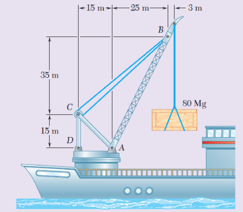
In the marine crane shown, link CD is known to have a uniform cross section of 50 × 150 mm. For the loading shown, determine the normal stress in the central portion of that link.
Fig. P1.59
The normal stress in the centre portion of the link.
Answer to Problem 59RP
The normal stress in the centre portion of the link is
Explanation of Solution
Given information:
The uniform cross section is
Calculation:
Sketch the free body diagram of ABC as shown in Figure 1.
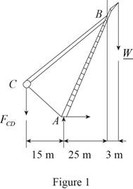
Here, W is the weight of the loading.
Find the weight of the loading as follows:
Here, m is the mass of the loading and g is the acceleration due to gravity.
Substitute
Taking moment about A,
Substitute
Find the area of the cross section using the relation:
Here, b is the width of the cross section and d is the depth of the cross section.
Substitute
Determine the normal stress in the central portion of the link as follows:
Here, A is the area of the cross section and
Substitute
Thus, the normal stress in the centre portion of the link is
Want to see more full solutions like this?
Chapter 1 Solutions
EBK MECHANICS OF MATERIALS


- 3-9. Given that the force acting on a particle has the following components: Fx = −x + y, Fy = x − y + y², F₂ = 0. Solve for the potential energy V. -arrow_forward2.5 (B). A steel rod of cross-sectional area 600 mm² and a coaxial copper tube of cross-sectional area 1000 mm² are firmly attached at their ends to form a compound bar. Determine the stress in the steel and in the copper when the temperature of the bar is raised by 80°C and an axial tensile force of 60 kN is applied. For steel, E = 200 GN/m² with x = 11 x 10-6 per °C. E = 100 GN/m² with α = 16.5 × 10⁻⁶ For copper, per °C. [E.I.E.] [94.6, 3.3 MN/m².]arrow_forward3–16. A particle of mass m is embedded at a distance R from the center of a massless circular disk of radius R which can roll without slipping on the inside surface of a fixed circular cylinder of radius 3R. The disk is released with zero velocity from the position shown and rolls because of gravity, all motion taking place in the same vertical plane. Find: (a) the maximum velocity of the particle during the resulting motion; (b) the reaction force acting on the disk at the point of contact when it is at its lowest position. KAR 60° 3R M Fig. P3-16arrow_forward
- I have figured out the support reactions, Ay = 240 kN, Ax = 0 kN, Ma = 639.2 kN*m and the constant term for V(x) is 240. I am not figuring out the function of x part right. Show how to derive V(x) and M(x) for this distributed load.arrow_forward2.4 (A). A 75 mm diameter compound bar is constructed by shrinking a circular brass bush onto the outside of a 50 mm diameter solid steel rod. If the compound bar is then subjected to an axial compressive load of 160 kN determine the load carried by the steel rod and the brass bush and the compressive stress set up in each material. For steel, E 210 GN/m²; for brass, E = 100 GN/m². [I. Struct. E.] [100.3, 59.7 kN; 51.1, 24.3 MN/m².]arrow_forward1.7 (A). A bar ABCD consists of three sections: AB is 25 mm square and 50 mm long, BC is of 20 mm diameter and 40 mm long and CD is of 12 mm diameter and 50 mm long. Determine the stress set up in each section of the bar when it is subjected to an axial tensile load of 20 kN. What will be the total extension of the bar under this load? For the bar material, E = 210GN/m2. [32,63.7, 176.8 MN/mZ, 0.062mrn.l 10:41 مarrow_forward
- 2.2 (A). If the maximum stress allowed in the copper of the cable of problem 2.1 is 60 MN/m2, determine the maximum tension which C3.75 kN.1 10:41 مarrow_forward1.1 (A). A 25mm squarecross-section bar of length 300mm carries an axial compressive load of 50kN. Determine the stress set up ip the bar and its change of length when the load is applied. For the bar material E = 200 GN/m2. [80 MN/m2; 0.12mm.larrow_forward2.1 (A). A power transmission cable consists of ten copper wires each of 1.6 mm diameter surrounding three steel wires each of 3 mm diameter. Determine the combined E for the compound cable and hence determine the extension of a 30 m length of the cable when it is being laid with a tension of 2 kN. For steel, E200 GN/mZ; for copper, E = 100 GN/mZ. C151.3 GN/mZ; 9.6 mm.] 10:41 مarrow_forward
- question 662 thank youarrow_forward1.5 (A). A simple turnbuckle arrangement is constructed from a 40 mm outside diameter tube threaded internally at each end to take two rods of 25 mm outside diameter with threaded ends. What will be the nominal stresses set up in the tube and the rods, ignoring thread depth, when the turnbuckle cames an axial load of 30 kN? Assuming a sufficient strength of thread, what maximum load can be transmitted by the turnbuckle if the maximum stress is limited to 180 MN/mz? C39.2, 61.1 MN/m2, 88.4 kN.1arrow_forward1.3 (A). Define the terms shear stress and shear strain, illustrating your answer by means of a simple sketch. Two circular bars, one of brass and the other of steel, are to be loaded by a shear load of 30 kN. Determine the necessary diameter of the bars (a) in single shear, (b) in double shear, if the shear stress in the two materials must not exceed 50 MN/m2 and 100 MN/ mZ respectively. C27.6, 19.5, 19.5, 13.8mm.l 11arrow_forward
 Elements Of ElectromagneticsMechanical EngineeringISBN:9780190698614Author:Sadiku, Matthew N. O.Publisher:Oxford University Press
 Mechanics of Materials (10th Edition)Mechanical EngineeringISBN:9780134319650Author:Russell C. HibbelerPublisher:PEARSON
 Thermodynamics: An Engineering ApproachMechanical EngineeringISBN:9781259822674Author:Yunus A. Cengel Dr., Michael A. BolesPublisher:McGraw-Hill Education
 Control Systems EngineeringMechanical EngineeringISBN:9781118170519Author:Norman S. NisePublisher:WILEY
 Mechanics of Materials (MindTap Course List)Mechanical EngineeringISBN:9781337093347Author:Barry J. Goodno, James M. GerePublisher:Cengage Learning
 Engineering Mechanics: StaticsMechanical EngineeringISBN:9781118807330Author:James L. Meriam, L. G. Kraige, J. N. BoltonPublisher:WILEY