
EBK MECHANICS OF MATERIALS
7th Edition
ISBN: 9780100257061
Author: BEER
Publisher: YUZU
expand_more
expand_more
format_list_bulleted
Concept explainers
Videos
Textbook Question
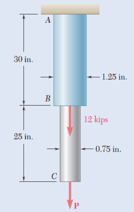
Chapter 1.2, Problem 4P
Two solid cylindrical rods AB and BC are welded together at B and loaded as shown. Determine the magnitude of the force P for which the tensile stresses in rods AB and BC are equal.
Fig. P1.3 and P1.4
Expert Solution & Answer

Trending nowThis is a popular solution!

Students have asked these similar questions
3
N2=28
P(diametral pitch)=8 for all gears
Coupled to 25 hp motor
N3=34
Full depth spur gears with pressure angle=20°
N₂=2000 rpm
(1) Compute the circular pitch, the center-to-center distance, and base circle radii.
(2) Draw the free body diagram of gear 3 and show all the forces and the torque.
(3) In mounting gears, the center-to-center distance was reduced by 0.1 inch.
Calculate the new values of center-to-center distance, pressure angle, base circle radii,
and pitch circle diameters.
(4)What is the new tangential and radial forces for gear 3?
(5) Under the new center to center distance, is the contact ratio (mc) increasing or
decreasing?
2. A flat belt drive consists of two 4-ft diameter cast-iron pulleys spaced 16 ft apart.
A power of 60 hp is transmitted by a pulley whose speed is 380 rev/min. Use a
service factor (Ks) pf 1.1 and a design factor 1.0. The width of the polyamide A-3
belt is 6 in. Use CD=1. Answer the following questions.
(1) What is the total length of the belt according to the given geometry?
(2) Find the centrifugal force (Fc) applied to the belt.
(3) What is the transmitted torque through the pulley system given 60hp?
(4) Using the allowable tension, find the force (F₁) on the tight side. What is the
tension at the loose side (F2) and the initial tension (F.)?
(5) Using the forces, estimate the developed friction coefficient (f)
(6) Based on the forces and the given rotational speed, rate the pulley set. In other
words, what is the horse power that can be transmitted by the pulley system?
(7) To reduce the applied tension on the tight side, the friction coefficient is
increased to 0.75. Find out the…
The tooth numbers for the gear train illustrated are N₂ = 24, N3 = 18, №4 = 30, №6 = 36, and
N₁ = 54. Gear 7 is fixed. If shaft b is turned through 5 revolutions, how many turns will shaft a make?
a
5
[6]
b
Chapter 1 Solutions
EBK MECHANICS OF MATERIALS
Ch. 1.2 - Two solid cylindrical rods AB and BC are welded...Ch. 1.2 - Two solid cylindrical rods AB and BC are welded...Ch. 1.2 - Two solid cylindrical rods AB and BC are welded...Ch. 1.2 - Two solid cylindrical rods AB and BC are welded...Ch. 1.2 - A strain gage located at C on the surface of bone...Ch. 1.2 - Two brass rods AB and BC, each of uniform...Ch. 1.2 - Each of the four vertical links has an 8 36-mm...Ch. 1.2 - Link AC has a uniform rectangular cross section 18...Ch. 1.2 - Three forces, each of magnitude P = 4 kN, are...Ch. 1.2 - Link BD consists of a single bar 1 in. wide and 12...
Ch. 1.2 - For the Pratt bridge truss and loading shown,...Ch. 1.2 - The frame shown consists of four wooden members,...Ch. 1.2 - An aircraft tow bar is positioned by means of a...Ch. 1.2 - Two hydraulic cylinders are used to control the...Ch. 1.2 - Determine the diameter of the largest circular...Ch. 1.2 - Two wooden planks, each 12 in. thick and 9 in....Ch. 1.2 - When the force P reached 1600 lb, the wooden...Ch. 1.2 - A load P is applied to a steel rod supported as...Ch. 1.2 - The axial force in the column supporting the...Ch. 1.2 - Three wooden planks are fastened together by a...Ch. 1.2 - A 40-kN axial load is applied to a short wooden...Ch. 1.2 - An axial load P is supported by a short W8 40...Ch. 1.2 - Link AB, of width b = 2 in. and thickness t=14...Ch. 1.2 - Determine the largest load P that can be applied...Ch. 1.2 - Knowing that = 40 and P = 9 kN, determine (a) the...Ch. 1.2 - The hydraulic cylinder CF, which partially...Ch. 1.2 - For the assembly and loading of Prob. 1.7,...Ch. 1.2 - Two identical linkage-and-hydraulic-cylinder...Ch. 1.5 - Two wooden members of uniform rectangular cross...Ch. 1.5 - Two wooden members of uniform rectangular cross...Ch. 1.5 - The 1.4-kip load P is supported by two wooden...Ch. 1.5 - Two wooden members of uniform cross section are...Ch. 1.5 - A centric load P is applied to the granite block...Ch. 1.5 - A 240-kip load P is applied to the granite block...Ch. 1.5 - A steel pipe of 400-mm outer diameter is...Ch. 1.5 - A steel pipe of 400-mm outer diameter is...Ch. 1.5 - A steel loop ABCD of length 5 ft and of 38-in....Ch. 1.5 - Link BC is 6 mm thick, has a width w = 25 mm, and...Ch. 1.5 - Link BC is 6 mm thick and is made of a steel with...Ch. 1.5 - Members AB and BC of the truss shown are made of...Ch. 1.5 - Members AB and BC of the truss shown are made of...Ch. 1.5 - Link AB is to be made of a steel for which the...Ch. 1.5 - Two wooden members are joined by plywood splice...Ch. 1.5 - For the joint and loading of Prob. 1.43, determine...Ch. 1.5 - Three 34-in.-diameter steel bolts are to be used...Ch. 1.5 - Three steel bolts are to be used to attach the...Ch. 1.5 - A load P is supported as shown by a steel pin that...Ch. 1.5 - A load P is supported as shown by a steel pin that...Ch. 1.5 - A steel plate 14 in. thick is embedded in a...Ch. 1.5 - Determine the factor of safety for the cable...Ch. 1.5 - Link AC is made of a steel with a 65-ksi ultimate...Ch. 1.5 - Solve Prob. 1.51, assuming that the structure has...Ch. 1.5 - Each of the two vertical links CF connecting the...Ch. 1.5 - Solve Prob. 1.53, assuming that the pins at C and...Ch. 1.5 - In the structure shown, an 8-mm-diameter pin is...Ch. 1.5 - In an alternative design for the structure of...Ch. 1.5 - Prob. 57PCh. 1.5 - The Load and Resistance Factor Design method is to...Ch. 1 - In the marine crane shown, link CD is known to...Ch. 1 - Two horizontal 5-kip forces are applied to pin B...Ch. 1 - For the assembly and loading of Prob. 1.60,...Ch. 1 - Two steel plates are to be held together by means...Ch. 1 - A couple M of magnitude 1500 N m is applied to...Ch. 1 - Knowing that link DE is 18 in. thick and 1 in....Ch. 1 - A 58-in.-diameter steel rod AB is fitted to a...Ch. 1 - In the steel structure shown, a 6-mm-diameter pin...Ch. 1 - Prob. 67RPCh. 1 - A force P is applied as shown to a steel...Ch. 1 - The two portions of member AB are glued together...Ch. 1 - The two portions of member AB are glued together...
Additional Engineering Textbook Solutions
Find more solutions based on key concepts
Porter’s competitive forces model: The model is used to provide a general view about the firms, the competitors...
Management Information Systems: Managing The Digital Firm (16th Edition)
How is the hydrodynamic entry length defined for flow in a pipe? Is the entry length longer in laminar or turbu...
Fluid Mechanics: Fundamentals and Applications
The solid steel shaft AC has a diameter of 25 mm and is supported by smooth bearings at D and E. It is coupled ...
Mechanics of Materials (10th Edition)
1.2 Explain the difference between geodetic and plane
surveys,
Elementary Surveying: An Introduction To Geomatics (15th Edition)
How does a computers main memory differ from its auxiliary memory?
Java: An Introduction to Problem Solving and Programming (8th Edition)
CONCEPT QUESTIONS
15.CQ3 The ball rolls without slipping on the fixed surface as shown. What is the direction ...
Vector Mechanics for Engineers: Statics and Dynamics
Knowledge Booster


Learn more about
Need a deep-dive on the concept behind this application? Look no further. Learn more about this topic, mechanical-engineering and related others by exploring similar questions and additional content below.Similar questions
- Please do not use any AI tools to solve this question. I need a fully manual, step-by-step solution with clear explanations, as if it were done by a human tutor. No AI-generated responses, please.arrow_forwardPlease do not use any AI tools to solve this question. I need a fully manual, step-by-step solution with clear explanations, as if it were done by a human tutor. No AI-generated responses, please.arrow_forwardCE-112 please solve this problem step by step and give me the correct answerarrow_forward
- CE-112 please solve this problem step by step and give me the correct asnwerarrow_forwardthis is an old practice exam, the answer is Ax = -4, Ay = -12,Az = 32.5, Bx= 34, Bz = 5, By = 0 but how?arrow_forwardThis is an old practice exam, the answer is Ax = Az = 0, Ay = 2000, TDE = 4750, Cx = 2000, Cy = 2000, Cz = -800 but how?arrow_forward
- this is an old practice exam, the answer is Fmin = 290.5lb but howarrow_forwardThis is an exam review question. The answer is Pmin = 622.9 lb but whyarrow_forwardPlease do not use any AI tools to solve this question. I need a fully manual, step-by-step solution with clear explanations, as if it were done by a human tutor. No AI-generated responses, please.arrow_forward
arrow_back_ios
SEE MORE QUESTIONS
arrow_forward_ios
Recommended textbooks for you
 International Edition---engineering Mechanics: St...Mechanical EngineeringISBN:9781305501607Author:Andrew Pytel And Jaan KiusalaasPublisher:CENGAGE L
 Mechanics of Materials (MindTap Course List)Mechanical EngineeringISBN:9781337093347Author:Barry J. Goodno, James M. GerePublisher:Cengage Learning
 Principles of Heat Transfer (Activate Learning wi...Mechanical EngineeringISBN:9781305387102Author:Kreith, Frank; Manglik, Raj M.Publisher:Cengage Learning
International Edition---engineering Mechanics: St...
Mechanical Engineering
ISBN:9781305501607
Author:Andrew Pytel And Jaan Kiusalaas
Publisher:CENGAGE L
Mechanics of Materials (MindTap Course List)
Mechanical Engineering
ISBN:9781337093347
Author:Barry J. Goodno, James M. Gere
Publisher:Cengage Learning
Principles of Heat Transfer (Activate Learning wi...
Mechanical Engineering
ISBN:9781305387102
Author:Kreith, Frank; Manglik, Raj M.
Publisher:Cengage Learning
EVERYTHING on Axial Loading Normal Stress in 10 MINUTES - Mechanics of Materials; Author: Less Boring Lectures;https://www.youtube.com/watch?v=jQ-fNqZWrNg;License: Standard YouTube License, CC-BY