
EBK MECHANICS OF MATERIALS
7th Edition
ISBN: 9780100257061
Author: BEER
Publisher: YUZU
expand_more
expand_more
format_list_bulleted
Concept explainers
Videos
Textbook Question
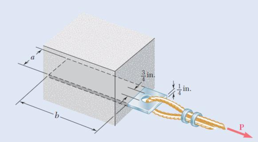
Chapter 1.5, Problem 49P
A steel plate
Fig. P1.49
Expert Solution & Answer
Want to see the full answer?
Check out a sample textbook solution
Students have asked these similar questions
(read image)
(read image)
(read me)
Chapter 1 Solutions
EBK MECHANICS OF MATERIALS
Ch. 1.2 - Two solid cylindrical rods AB and BC are welded...Ch. 1.2 - Two solid cylindrical rods AB and BC are welded...Ch. 1.2 - Two solid cylindrical rods AB and BC are welded...Ch. 1.2 - Two solid cylindrical rods AB and BC are welded...Ch. 1.2 - A strain gage located at C on the surface of bone...Ch. 1.2 - Two brass rods AB and BC, each of uniform...Ch. 1.2 - Each of the four vertical links has an 8 36-mm...Ch. 1.2 - Link AC has a uniform rectangular cross section 18...Ch. 1.2 - Three forces, each of magnitude P = 4 kN, are...Ch. 1.2 - Link BD consists of a single bar 1 in. wide and 12...
Ch. 1.2 - For the Pratt bridge truss and loading shown,...Ch. 1.2 - The frame shown consists of four wooden members,...Ch. 1.2 - An aircraft tow bar is positioned by means of a...Ch. 1.2 - Two hydraulic cylinders are used to control the...Ch. 1.2 - Determine the diameter of the largest circular...Ch. 1.2 - Two wooden planks, each 12 in. thick and 9 in....Ch. 1.2 - When the force P reached 1600 lb, the wooden...Ch. 1.2 - A load P is applied to a steel rod supported as...Ch. 1.2 - The axial force in the column supporting the...Ch. 1.2 - Three wooden planks are fastened together by a...Ch. 1.2 - A 40-kN axial load is applied to a short wooden...Ch. 1.2 - An axial load P is supported by a short W8 40...Ch. 1.2 - Link AB, of width b = 2 in. and thickness t=14...Ch. 1.2 - Determine the largest load P that can be applied...Ch. 1.2 - Knowing that = 40 and P = 9 kN, determine (a) the...Ch. 1.2 - The hydraulic cylinder CF, which partially...Ch. 1.2 - For the assembly and loading of Prob. 1.7,...Ch. 1.2 - Two identical linkage-and-hydraulic-cylinder...Ch. 1.5 - Two wooden members of uniform rectangular cross...Ch. 1.5 - Two wooden members of uniform rectangular cross...Ch. 1.5 - The 1.4-kip load P is supported by two wooden...Ch. 1.5 - Two wooden members of uniform cross section are...Ch. 1.5 - A centric load P is applied to the granite block...Ch. 1.5 - A 240-kip load P is applied to the granite block...Ch. 1.5 - A steel pipe of 400-mm outer diameter is...Ch. 1.5 - A steel pipe of 400-mm outer diameter is...Ch. 1.5 - A steel loop ABCD of length 5 ft and of 38-in....Ch. 1.5 - Link BC is 6 mm thick, has a width w = 25 mm, and...Ch. 1.5 - Link BC is 6 mm thick and is made of a steel with...Ch. 1.5 - Members AB and BC of the truss shown are made of...Ch. 1.5 - Members AB and BC of the truss shown are made of...Ch. 1.5 - Link AB is to be made of a steel for which the...Ch. 1.5 - Two wooden members are joined by plywood splice...Ch. 1.5 - For the joint and loading of Prob. 1.43, determine...Ch. 1.5 - Three 34-in.-diameter steel bolts are to be used...Ch. 1.5 - Three steel bolts are to be used to attach the...Ch. 1.5 - A load P is supported as shown by a steel pin that...Ch. 1.5 - A load P is supported as shown by a steel pin that...Ch. 1.5 - A steel plate 14 in. thick is embedded in a...Ch. 1.5 - Determine the factor of safety for the cable...Ch. 1.5 - Link AC is made of a steel with a 65-ksi ultimate...Ch. 1.5 - Solve Prob. 1.51, assuming that the structure has...Ch. 1.5 - Each of the two vertical links CF connecting the...Ch. 1.5 - Solve Prob. 1.53, assuming that the pins at C and...Ch. 1.5 - In the structure shown, an 8-mm-diameter pin is...Ch. 1.5 - In an alternative design for the structure of...Ch. 1.5 - Prob. 57PCh. 1.5 - The Load and Resistance Factor Design method is to...Ch. 1 - In the marine crane shown, link CD is known to...Ch. 1 - Two horizontal 5-kip forces are applied to pin B...Ch. 1 - For the assembly and loading of Prob. 1.60,...Ch. 1 - Two steel plates are to be held together by means...Ch. 1 - A couple M of magnitude 1500 N m is applied to...Ch. 1 - Knowing that link DE is 18 in. thick and 1 in....Ch. 1 - A 58-in.-diameter steel rod AB is fitted to a...Ch. 1 - In the steel structure shown, a 6-mm-diameter pin...Ch. 1 - Prob. 67RPCh. 1 - A force P is applied as shown to a steel...Ch. 1 - The two portions of member AB are glued together...Ch. 1 - The two portions of member AB are glued together...
Knowledge Booster


Learn more about
Need a deep-dive on the concept behind this application? Look no further. Learn more about this topic, mechanical-engineering and related others by exploring similar questions and additional content below.Similar questions
- (read me)arrow_forward(read image)arrow_forwardQu. 13 What are the indices for the Direction 2 indicated by vector in the following sketch? Qu. 14 Determine the indices for the direction A and B shown in the following cubic unit cell. please show all work step by step from material engineeringarrow_forward
- The thin-walled open cross section shown is transmitting torque 7. The angle of twist ₁ per unit length of each leg can be determined separately using the equation 01 = 3Ti GLIC 3 where G is the shear modulus, ₁ is the angle of twist per unit length, T is torque, and L is the length of the median line. In this case, i = 1, 2, 3, and T; represents the torque in leg i. Assuming that the angle of twist per unit length for each leg is the same, show that T= Lic³ and Tmaz = G01 Cmax Consider a steel section with Tallow = 12.40 kpsi. C1 2 mm L1 20 mm C2 3 mm L2 30 mm C3 2 mm L3 25 mm Determine the torque transmitted by each leg and the torque transmitted by the entire section. The torque transmitted by the first leg is | N-m. The torque transmitted by the second leg is N-m. The torque transmitted by the third leg is N-m. The torque transmitted by the entire section is N-m.arrow_forwardPlease help, make sure it's to box out and make it clear what answers go where...arrow_forwardThe cylinder floats in the water and oil to the level shown. Determine the weight of the cylinder. (rho)o=910 kg/m^3arrow_forward
arrow_back_ios
SEE MORE QUESTIONS
arrow_forward_ios
Recommended textbooks for you
 Elements Of ElectromagneticsMechanical EngineeringISBN:9780190698614Author:Sadiku, Matthew N. O.Publisher:Oxford University Press
 Mechanics of Materials (10th Edition)Mechanical EngineeringISBN:9780134319650Author:Russell C. HibbelerPublisher:PEARSON
 Thermodynamics: An Engineering ApproachMechanical EngineeringISBN:9781259822674Author:Yunus A. Cengel Dr., Michael A. BolesPublisher:McGraw-Hill Education
 Control Systems EngineeringMechanical EngineeringISBN:9781118170519Author:Norman S. NisePublisher:WILEY
 Mechanics of Materials (MindTap Course List)Mechanical EngineeringISBN:9781337093347Author:Barry J. Goodno, James M. GerePublisher:Cengage Learning
 Engineering Mechanics: StaticsMechanical EngineeringISBN:9781118807330Author:James L. Meriam, L. G. Kraige, J. N. BoltonPublisher:WILEY
Elements Of Electromagnetics
Mechanical Engineering
ISBN:9780190698614
Author:Sadiku, Matthew N. O.
Publisher:Oxford University Press
Mechanics of Materials (10th Edition)
Mechanical Engineering
ISBN:9780134319650
Author:Russell C. Hibbeler
Publisher:PEARSON
Thermodynamics: An Engineering Approach
Mechanical Engineering
ISBN:9781259822674
Author:Yunus A. Cengel Dr., Michael A. Boles
Publisher:McGraw-Hill Education
Control Systems Engineering
Mechanical Engineering
ISBN:9781118170519
Author:Norman S. Nise
Publisher:WILEY
Mechanics of Materials (MindTap Course List)
Mechanical Engineering
ISBN:9781337093347
Author:Barry J. Goodno, James M. Gere
Publisher:Cengage Learning
Engineering Mechanics: Statics
Mechanical Engineering
ISBN:9781118807330
Author:James L. Meriam, L. G. Kraige, J. N. Bolton
Publisher:WILEY
EVERYTHING on Axial Loading Normal Stress in 10 MINUTES - Mechanics of Materials; Author: Less Boring Lectures;https://www.youtube.com/watch?v=jQ-fNqZWrNg;License: Standard YouTube License, CC-BY