
EBK MECHANICS OF MATERIALS
7th Edition
ISBN: 9780100257061
Author: BEER
Publisher: YUZU
expand_more
expand_more
format_list_bulleted
Videos
Textbook Question
Chapter 1.5, Problem 31P
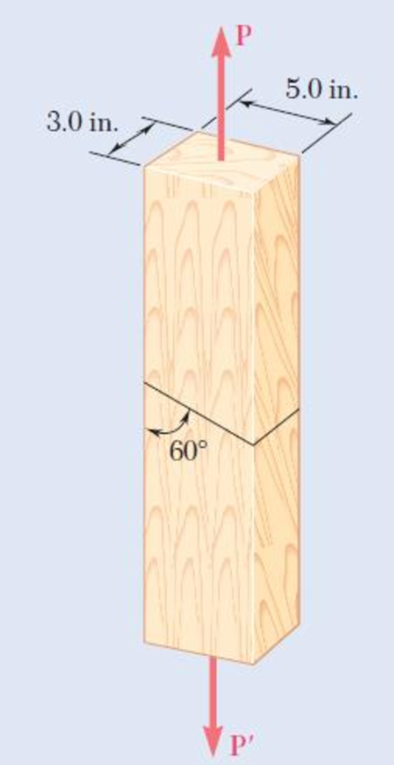
The 1.4-kip load P is supported by two wooden members of uniform cross section that are joined by the simple glued scarf splice shown. Determine the normal and shearing stresses in the glued splice.
Fig. P1.31 and P1.32
Expert Solution & Answer
Want to see the full answer?
Check out a sample textbook solution
Students have asked these similar questions
Procedure:1- Cartesian system, 2D3D,type of support2- Free body diagram3 - Find the support reactions4- If you find a negativenumber then flip the force5- Find the internal force3D∑Fx=0∑Fy=0∑Fz=0∑Mx=0∑My=0\Sigma Mz=02D\Sigma Fx=0\Sigma Fy=0\Sigma Mz=05- Use method of sectionand cut the elementwhere you want to find
Procedure:1- Cartesian system, 2D3D,type of support2- Free body diagram3 - Find the support reactions4- If you find a negativenumber then flip the force5- Find the internal force3D∑Fx=0∑Fy=0∑Fz=0∑Mx=0∑My=0\Sigma Mz=02D\Sigma Fx=0\Sigma Fy=0\Sigma Mz=05- Use method of sectionand cut the elementwhere you want to findthe internal force andkeep either side of the
Procedure:
1- Cartesian system, 2D3D,
type of support
2- Free body diagram
3 - Find the support reactions
4- If you find a negative
number then flip the force
5- Find the internal force
3D
∑Fx=0
∑Fy=0
∑Fz=0
∑Mx=0
∑My=0
ΣMz=0
2D
ΣFx=0
ΣFy=0
ΣMz=0
5- Use method of section
and cut the element
where you want to find
the internal force and
keep either side of the
Chapter 1 Solutions
EBK MECHANICS OF MATERIALS
Ch. 1.2 - Two solid cylindrical rods AB and BC are welded...Ch. 1.2 - Two solid cylindrical rods AB and BC are welded...Ch. 1.2 - Two solid cylindrical rods AB and BC are welded...Ch. 1.2 - Two solid cylindrical rods AB and BC are welded...Ch. 1.2 - A strain gage located at C on the surface of bone...Ch. 1.2 - Two brass rods AB and BC, each of uniform...Ch. 1.2 - Each of the four vertical links has an 8 36-mm...Ch. 1.2 - Link AC has a uniform rectangular cross section 18...Ch. 1.2 - Three forces, each of magnitude P = 4 kN, are...Ch. 1.2 - Link BD consists of a single bar 1 in. wide and 12...
Ch. 1.2 - For the Pratt bridge truss and loading shown,...Ch. 1.2 - The frame shown consists of four wooden members,...Ch. 1.2 - An aircraft tow bar is positioned by means of a...Ch. 1.2 - Two hydraulic cylinders are used to control the...Ch. 1.2 - Determine the diameter of the largest circular...Ch. 1.2 - Two wooden planks, each 12 in. thick and 9 in....Ch. 1.2 - When the force P reached 1600 lb, the wooden...Ch. 1.2 - A load P is applied to a steel rod supported as...Ch. 1.2 - The axial force in the column supporting the...Ch. 1.2 - Three wooden planks are fastened together by a...Ch. 1.2 - A 40-kN axial load is applied to a short wooden...Ch. 1.2 - An axial load P is supported by a short W8 40...Ch. 1.2 - Link AB, of width b = 2 in. and thickness t=14...Ch. 1.2 - Determine the largest load P that can be applied...Ch. 1.2 - Knowing that = 40 and P = 9 kN, determine (a) the...Ch. 1.2 - The hydraulic cylinder CF, which partially...Ch. 1.2 - For the assembly and loading of Prob. 1.7,...Ch. 1.2 - Two identical linkage-and-hydraulic-cylinder...Ch. 1.5 - Two wooden members of uniform rectangular cross...Ch. 1.5 - Two wooden members of uniform rectangular cross...Ch. 1.5 - The 1.4-kip load P is supported by two wooden...Ch. 1.5 - Two wooden members of uniform cross section are...Ch. 1.5 - A centric load P is applied to the granite block...Ch. 1.5 - A 240-kip load P is applied to the granite block...Ch. 1.5 - A steel pipe of 400-mm outer diameter is...Ch. 1.5 - A steel pipe of 400-mm outer diameter is...Ch. 1.5 - A steel loop ABCD of length 5 ft and of 38-in....Ch. 1.5 - Link BC is 6 mm thick, has a width w = 25 mm, and...Ch. 1.5 - Link BC is 6 mm thick and is made of a steel with...Ch. 1.5 - Members AB and BC of the truss shown are made of...Ch. 1.5 - Members AB and BC of the truss shown are made of...Ch. 1.5 - Link AB is to be made of a steel for which the...Ch. 1.5 - Two wooden members are joined by plywood splice...Ch. 1.5 - For the joint and loading of Prob. 1.43, determine...Ch. 1.5 - Three 34-in.-diameter steel bolts are to be used...Ch. 1.5 - Three steel bolts are to be used to attach the...Ch. 1.5 - A load P is supported as shown by a steel pin that...Ch. 1.5 - A load P is supported as shown by a steel pin that...Ch. 1.5 - A steel plate 14 in. thick is embedded in a...Ch. 1.5 - Determine the factor of safety for the cable...Ch. 1.5 - Link AC is made of a steel with a 65-ksi ultimate...Ch. 1.5 - Solve Prob. 1.51, assuming that the structure has...Ch. 1.5 - Each of the two vertical links CF connecting the...Ch. 1.5 - Solve Prob. 1.53, assuming that the pins at C and...Ch. 1.5 - In the structure shown, an 8-mm-diameter pin is...Ch. 1.5 - In an alternative design for the structure of...Ch. 1.5 - Prob. 57PCh. 1.5 - The Load and Resistance Factor Design method is to...Ch. 1 - In the marine crane shown, link CD is known to...Ch. 1 - Two horizontal 5-kip forces are applied to pin B...Ch. 1 - For the assembly and loading of Prob. 1.60,...Ch. 1 - Two steel plates are to be held together by means...Ch. 1 - A couple M of magnitude 1500 N m is applied to...Ch. 1 - Knowing that link DE is 18 in. thick and 1 in....Ch. 1 - A 58-in.-diameter steel rod AB is fitted to a...Ch. 1 - In the steel structure shown, a 6-mm-diameter pin...Ch. 1 - Prob. 67RPCh. 1 - A force P is applied as shown to a steel...Ch. 1 - The two portions of member AB are glued together...Ch. 1 - The two portions of member AB are glued together...
Knowledge Booster


Learn more about
Need a deep-dive on the concept behind this application? Look no further. Learn more about this topic, mechanical-engineering and related others by exploring similar questions and additional content below.Similar questions
- Procedure:1- Cartesian system, 2D3D,type of support2- Free body diagram3 - Find the support reactions4- If you find a negativenumber then flip the force5- Find the internal force3D∑Fx=0∑Fy=0∑Fz=0∑Mx=0∑My=0\Sigma Mz=02D\Sigma Fx=0\Sigma Fy=0\Sigma Mz=05- Use method of sectionand cut the elementwhere you want to findthe internal force andkeep either side of thearrow_forwardProcedure: 1- Cartesian system, 2(D)/(3)D, type of support 2- Free body diagram 3 - Find the support reactions 4- If you find a negative number then flip the force 5- Find the internal force 3D \sum Fx=0 \sum Fy=0 \sum Fz=0 \sum Mx=0 \sum My=0 \Sigma Mz=0 2D \Sigma Fx=0 \Sigma Fy=0 \Sigma Mz=0 5- Use method of section and cut the element where you want to find the internal force and keep either side of the sectionarrow_forwardProcedure: 1- Cartesian system, 2(D)/(3)D, type of support 2- Free body diagram 3 - Find the support reactions 4- If you find a negative number then flip the force 5- Find the internal force 3D \sum Fx=0 \sum Fy=0 \sum Fz=0 \sum Mx=0 \sum My=0 \Sigma Mz=0 2D \Sigma Fx=0 \Sigma Fy=0 \Sigma Mz=0 5- Use method of section and cut the element where you want to find the internal force and keep either side of the sectionarrow_forward
- For each system below with transfer function G(s), plot the pole(s) on the s-plane. and indicate whether the system is: (a) "stable" (i.e., a bounded input will always result in a bounded output), (b) "marginally stable," or (c) "unstable" Sketch a rough graph of the time response to a step input. 8 a) G(s) = 5-5 8 b) G(s) = c) G(s) = = s+5 3s + 8 s² - 2s +2 3s +8 d) G(s): = s²+2s+2 3s+8 e) G(s): = s² +9 f) G(s): 8 00 == Sarrow_forwardPlease answer the following question. Include all work and plase explain. Graphs are provided below. "Consider the Mg (Magnesium) - Ni (Nickel) phase diagram shown below. This phase diagram contains two eutectic reactions and two intermediate phases (Mg2Ni and MgNi2). At a temperature of 505oC, determine what the composition of an alloy would need to be to contain a mass fraction of 0.20 Mg and 0.80 Mg2Ni."arrow_forwardThe triangular plate, having a 90∘∘ angle at AA, supports the load PP = 370 lblb as shown in (Figure 1).arrow_forward
- Design a 4-bar linkage to carry the body in Figure 1 through the two positions P1 and P2 at the angles shown in the figure. Use analytical synthesis with the free choice values z = 1.075, q= 210°, ß2 = −27° for left side and s = 1.24, y= 74°, ½ = − 40° for right side. φ 1.236 P2 147.5° 210° 2.138 P1 Figure 1 Xarrow_forwardDesign a 4-bar linkage to carry the body in Figure 1 through the two positions P1 and P2 at the angles shown in the figure. Use analytical synthesis with the free choice values z = 1.075, q= 210°, B₂ = −27° for left side and s = 1.24, y= 74°, ½ = − 40° for right side. 1.236 P2 147.5° 210° P1 Figure 1 2.138 Xarrow_forwardcan you explain how in a coordinate frame transformation: v = {v_n}^T {n-hat} and then it was found that {n-hat} = [C]^T {b-hat} so v_n = {v_n}^T [C]^T {b-hat}, how does that equation go from that to this --> v_n = [C]^T v_barrow_forward
- 6) If (k = 0,7 cm) find Imax for figure below. 225mm 100mm ثلاثاء. 100mm 150mm 75mm Ans: Tmax=45:27 N/cm F-400 Narrow_forwardThe man has a weight W and stands halfway along the beam. The beam is not smooth, but the planes at A and B are smooth (and plane A is horizontal). Determine the magnitude of the tension in the cord in terms of W and θ.arrow_forwardDetermine the reactions at the two supports for this plate. Express the reactions in Cartesian vector form.arrow_forward
arrow_back_ios
SEE MORE QUESTIONS
arrow_forward_ios
Recommended textbooks for you
 Elements Of ElectromagneticsMechanical EngineeringISBN:9780190698614Author:Sadiku, Matthew N. O.Publisher:Oxford University Press
 Mechanics of Materials (10th Edition)Mechanical EngineeringISBN:9780134319650Author:Russell C. HibbelerPublisher:PEARSON
 Thermodynamics: An Engineering ApproachMechanical EngineeringISBN:9781259822674Author:Yunus A. Cengel Dr., Michael A. BolesPublisher:McGraw-Hill Education
 Control Systems EngineeringMechanical EngineeringISBN:9781118170519Author:Norman S. NisePublisher:WILEY
 Mechanics of Materials (MindTap Course List)Mechanical EngineeringISBN:9781337093347Author:Barry J. Goodno, James M. GerePublisher:Cengage Learning
 Engineering Mechanics: StaticsMechanical EngineeringISBN:9781118807330Author:James L. Meriam, L. G. Kraige, J. N. BoltonPublisher:WILEY
Elements Of Electromagnetics
Mechanical Engineering
ISBN:9780190698614
Author:Sadiku, Matthew N. O.
Publisher:Oxford University Press
Mechanics of Materials (10th Edition)
Mechanical Engineering
ISBN:9780134319650
Author:Russell C. Hibbeler
Publisher:PEARSON
Thermodynamics: An Engineering Approach
Mechanical Engineering
ISBN:9781259822674
Author:Yunus A. Cengel Dr., Michael A. Boles
Publisher:McGraw-Hill Education
Control Systems Engineering
Mechanical Engineering
ISBN:9781118170519
Author:Norman S. Nise
Publisher:WILEY
Mechanics of Materials (MindTap Course List)
Mechanical Engineering
ISBN:9781337093347
Author:Barry J. Goodno, James M. Gere
Publisher:Cengage Learning
Engineering Mechanics: Statics
Mechanical Engineering
ISBN:9781118807330
Author:James L. Meriam, L. G. Kraige, J. N. Bolton
Publisher:WILEY
An Introduction to Stress and Strain; Author: The Efficient Engineer;https://www.youtube.com/watch?v=aQf6Q8t1FQE;License: Standard YouTube License, CC-BY