
EBK FUNDAMENTALS OF ELECTRIC CIRCUITS
6th Edition
ISBN: 8220102801448
Author: Alexander
Publisher: YUZU
expand_more
expand_more
format_list_bulleted
Concept explainers
Videos
Textbook Question
Chapter 4, Problem 78P
Use PSpice or MultiSim to solve Prob. 4.52.
Expert Solution & Answer
Want to see the full answer?
Check out a sample textbook solution
Students have asked these similar questions
Find the operating point and the load line of a voltage-divider JFET biasing circuit
using the following parameters: VGS(0) = -1.3 and Vcc = 15 volts. Assume
ipss = 20 mA, RG₁ = RG2 = 10 kn, RD = 300, and Rs = 1 kn. Use Fig. 4b for
the IV characteristic of the JFET.
20nA
GS=-1.3 GS
10nA-
50
100
150
200
ID(J1)
UDS
Fig. 4b. The IV characteristics of an n-channel JFET (J113). The plots are for VGs increments of
0.05 volts. VGS(0) -1.3. The yellow and blue load lines are for examples 2 &3,
respectively.
Design the JFET circuit for the largest in swing. Use the self-bias circuit shown in
Fig. 6. Assume that VGS (0) = -1.3 and Vcc = 15 volts. Furthermore, assume that
ipss = 20 mA. Using Fig. 4b, draw the load line and identify the Q point. Explain
why this will allow the largest swing. Use ip = ipss (1-
VGS
VGS(0)
to show what
happens to i, and vps when you have a swing of 0.2 volts in vcs form its operating
point (that is, change vas by ±0.2 volts and compute the corresponding
iD and VDs).
RD
RG
Rs
0
20nA
GS=-1.3 VGS
12
10nA
-0-
Fig. 6. Circuit for Examples 2 &3.
BA-C
50
100
150
200
□ ID(J1)
UDS
Fig. 4b. The IV characteristics of an n-channel JFET (J113). The plots are for VGs increments of
0.05 volts. VGS(0) -1.3. The yellow and blue load lines are for examples 2 &3,
respectively.
please do the correct VI chrastaristics curve on excel. I am not sure if mine is correct
Chapter 4 Solutions
EBK FUNDAMENTALS OF ELECTRIC CIRCUITS
Ch. 4.2 - Figure 4.3 For Practice Prob. 4.1. For the circuit...Ch. 4.2 - Figure 4.5 For Practice Prob. 4.2. Assume that Vo...Ch. 4.3 - Figure 4.8 Using the superposition theorem, find...Ch. 4.3 - Figure 4.11 Use superposition to find vx in the...Ch. 4.3 - Find I in the circuit of Fig. 4.14 using the...Ch. 4.4 - Find io in the circuit of Fig. 4.19 using source...Ch. 4.4 - Use source transformation to find ix in the...Ch. 4.5 - Using Thevenins theorem, find the equivalent...Ch. 4.5 - Find the Thevenin equivalent circuit of the...Ch. 4.5 - Obtain the Thevenin equivalent of the circuit in...
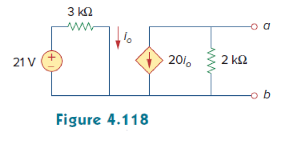
Ch. 4.6 - Find the Norton equivalent circuit for the circuit...Ch. 4.6 - Find the Norton equivalent circuit of the circuit...Ch. 4.8 - Determine the value of RL that will draw the...Ch. 4.9 - Rework Practice Prob. 4.9 using PSpice. Find the...Ch. 4.9 - Fin d the maximum power transferred to RL if the...Ch. 4.10 - The measured open-circuit voltage across a certain...Ch. 4.10 - Prob. 17PPCh. 4.10 - Obtain the current through the galvanometer,...Ch. 4 - The current through a branch in a linear network...Ch. 4 - For superposition, it is not required that only...Ch. 4 - The superposition principle applies to power...Ch. 4 - Refer to Fig. 4.67. The Thevenin resistance at...Ch. 4 - The Thevenin voltage across terminals a and b of...Ch. 4 - The Norton current at terminals a and b of the...Ch. 4 - The Norton resistance RN is exactly equal to the...Ch. 4 - Which pair of circuits in Fig. 4.68 are...Ch. 4 - A load is connected to a network. At the terminals...Ch. 4 - The source is supplying the maximum power to the...Ch. 4 - Calculate the current io in the circuit of Fig....Ch. 4 - Using Fig. 4.70, design a problem to help other...Ch. 4 - (a) In the circuit of Fig. 4.71, calculate vo and...Ch. 4 - Use linearity to determine io in the circuit of...Ch. 4 - For the circuit in Fig. 4.73, assume vo = 1 V, and...Ch. 4 - For the linear circuit shown in Fig. 4.74, use...Ch. 4 - Use linearity and the assumption that Vo = 1 V to...Ch. 4 - Using superposition, find Vo in the circuit of...Ch. 4 - Given that I = 6 amps when Vs = 160 volts and Is =...Ch. 4 - Using Fig. 4.78, design a problem to help other...Ch. 4 - Use the superposition principle to find io and vo...Ch. 4 - Determine vo in the circuit of Fig. 4.80 using the...Ch. 4 - Use superposition to find vo in the circuit of...Ch. 4 - Apply the superposition principle to find vo in...Ch. 4 - For the circuit in Fig. 4.83, use superposition to...Ch. 4 - Given the circuit in Fig. 4.84, use superposition...Ch. 4 - Use superposition to obtain vx in the circuit of...Ch. 4 - Use superposition to find Vo in the circuit of...Ch. 4 - Use superposition to solve for vx in the circuit...Ch. 4 - Use source transformation to reduce the circuit...Ch. 4 - Using Fig. 4.89, design a problem to help other...Ch. 4 - For the circuit in Fig, 4.90, use source...Ch. 4 - Referring to Fig. 4.91, use source transformation...Ch. 4 - Use source transformation to find the voltage Vx...Ch. 4 - Obtain vo in the circuit of Fig. 4.93 using source...Ch. 4 - Use source transformation to find io in the...Ch. 4 - Apply source transformation to find vx in the...Ch. 4 - Use source transformation to find Io in Fig. 4.96....Ch. 4 - Use source transformation to find vo in the...Ch. 4 - Use source transformation on the circuit shown in...Ch. 4 - Determine vx in the circuit of Fig. 4.99 using...Ch. 4 - Use source transformation to find ix in the...Ch. 4 - Determine the Thevenin equivalent circuit, shown...Ch. 4 - Using Fig. 4.102, design a problem that will help...Ch. 4 - Use Thevenins theorem to find vo in Prob. 4.12....Ch. 4 - Solve for the current i in the circuit of Fig....Ch. 4 - Find the Norton equivalent with respect to...Ch. 4 - Apply Thevenins theorem to find Vo in the circuit...Ch. 4 - Obtain the Thevenin equivalent at terminals a-b of...Ch. 4 - Find the Thevenin equivalent at terminals a-b of...Ch. 4 - Find the Thevenin and Norton equivalents at...Ch. 4 - For the circuit in Fig. 4.109, find the Thevenin...Ch. 4 - Find the Thevenin equivalent looking into...Ch. 4 - For the circuit in Fig. 4.111, obtain the Thevenin...Ch. 4 - Find the Thevenin equivalent of the circuit in...Ch. 4 - Using Fig. 4.113, design a problem to help other...Ch. 4 - Obtain the Thevenin and Norton equivalent circuits...Ch. 4 - Determine the Norton equivalent at terminals a-b...Ch. 4 - Find the Norton equivalent looking into terminals...Ch. 4 - Obtain the Norton equivalent of the circuit in...Ch. 4 - Given the circuit in Fig. 4.117, obtain the Norton...Ch. 4 - For the transistor model in Fig. 4.118, obtain the...Ch. 4 - Find the Norton equivalent at terminals a-b of the...Ch. 4 - Find the Thevenin equivalent between terminals a-b...Ch. 4 - Obtain the Norton equivalent at terminals a-b of...Ch. 4 - Use Nortons theorem to find Vo in the circuit of...Ch. 4 - Obtain the Thevenin and Norton equivalent circuits...Ch. 4 - The network in Fig. 4.124 models a bipolar...Ch. 4 - Determine the Thevenin and Norton equivalents at...Ch. 4 - For the circuit in Fig. 4.126, find the Thevenin...Ch. 4 - Obtain the Thevenin and Norton equivalent circuits...Ch. 4 - Find the Thevenin equivalent of the circuit in...Ch. 4 - Find the Norton equivalent for the circuit in Fig....Ch. 4 - Obtain the Thevenin equivalent seen at terminals...Ch. 4 - For the circuit shown in Fig. 4.131, determine the...Ch. 4 - Find the maximum power that can be delivered to...Ch. 4 - The variable resistor R in Fig. 4.133 is adjusted...Ch. 4 - Consider the 30- resistor in Fig. 4.134. First...Ch. 4 - Find the maximum power transferred to resistor R...Ch. 4 - Determine the maximum power delivered to the...Ch. 4 - For the circuit in Fig. 4.137, what resistor...Ch. 4 - (a) For the circuit in Fig. 4.138, obtain the...Ch. 4 - Determine the maximum power that can be delivered...Ch. 4 - For the bridge circuit shown in Fig. 4.140, find...Ch. 4 - For the circuit in Fig. 4.141, determine the value...Ch. 4 - Solve Prob. 4.34 using PSpice or MultiSim. Let V =...Ch. 4 - Use PSpice or MultiSim to solve Prob. 4.44. For...Ch. 4 - Use PSpice or MultiSim to solve Prob. 4.52.Ch. 4 - Obtain the Thevenin equivalent of the circuit in...Ch. 4 - Use PSpice or MultiSim to find the Thevenin...Ch. 4 - For the circuit in Fig. 4.126, use PSpice or...Ch. 4 - An automobile battery has an open circuit voltage...Ch. 4 - The following results were obtained from...Ch. 4 - When connected to a 4- resistor, a battery has a...Ch. 4 - The Thevenin equivalent at terminals a-b of the...Ch. 4 - A black box with a circuit in it is connected to a...Ch. 4 - A transducer is modeled with a current source Is...Ch. 4 - Consider the circuit in Fig. 4.144. An ammeter...Ch. 4 - Consider the circuit in Fig. 4.145. (a) Replace...Ch. 4 - The Wheatstone bridge circuit shown in Fig. 4.146...Ch. 4 - (a) In the Wheatstone bridge circuit of Fig. 4.147...Ch. 4 - Consider the bridge circuit of Fig. 4.148. Is the...Ch. 4 - The circuit in Fig. 4.149 models a common-emitter...Ch. 4 - An attenuator is an interface circuit that reduces...Ch. 4 - A dc voltmeter with a sensitivity of 10 k/V is...Ch. 4 - A resistance array is connected to a load resistor...Ch. 4 - A common-emitter amplifier circuit is shown in...Ch. 4 - For Practice Prob. 4.18, determine the current...
Knowledge Booster


Learn more about
Need a deep-dive on the concept behind this application? Look no further. Learn more about this topic, electrical-engineering and related others by exploring similar questions and additional content below.Similar questions
- please do the correct VI chrastaristics curve on excel. I am not sure if mine is correct. Note the two curves in the picture are for both but its two tries and i dont know which is correct, and probebly both are wrong SCR (Forward Bias Condition) NO VAA VG= 0V, IG=0 mA VG= 5V, IG=4.07mA VG= 10V, IG=9.05mA VAK (V) IAK(mA) VAK (V) IAK(mA) VAK (V) IAK(mA) 1 0 0 0 0 0 0 0 2 5 0.576 4.42 mA 0.576 4.42 mA 0.576 4.43 3 10 7.99 2 0.598 9.4 0.598 9.4 4 15 14.99 0.003 0.612 14.4 0.612 14.4 5 20 19.994 0.004 0.622 19.4 0.622 19.4 6 25 0.63 24.4 0.63 24.4 0.63 24.4 4 30 0.637 29.4 0.637 29.4 0.637 29.4 8 40 0.65 39.4 0.65 39.4 0.65 39.4 9 50 0.66 49.3 0.66 49.3 0.66 49.3 10 60 0.67 59.3 0.67 59.3 0.67 59.3 11 70 0.679 69.3 0.679 69.3 SCR (Reversed Bias…arrow_forwardSee both images attachedarrow_forwardSee both images to understandarrow_forward
- Please see both images to answerarrow_forwardfeedback and open-loop gains. R2 RI =B=S Vi name the circuit, derive and find the oscillation RA Ca Rx 000arrow_forward5 Find the value of voltage Vy using nodal analysis (write and then solve the set of equations to get voltage Vx from your variables.) 43 LX + Vx да ww 1 23 дъх 83 38 wwarrow_forward
- help on this question about block diagram reduction?arrow_forward4) Find the valve of current if using nodal analys.3. (write and then solve the set of equations toget current Ex from your voltage variables.) M 3 ча + GA हुप 8Aarrow_forward2) Write but do not solve the set of Nodal equations for this circuit. 35 34 M x www 2 3A ↑ -+ 1v {7 ww 6 Bixarrow_forward
- 3) Write: but do not solve the set of Nodal equations. for this circuit. m 4 13 35 23 ZA 5 M 8V (±) 6arrow_forwardFeedback and open-loop gains. کا ✓ = B= S R1 ww C1 C2 R2 ww derive the oscillation frequency,arrow_forward1) Write but do not solve the set of Nodal equations for this circuit. 12 m 8 4A √3 ww www 6 ±7V 5 हुप Дам V 1 3 mmm 2Aarrow_forward
arrow_back_ios
SEE MORE QUESTIONS
arrow_forward_ios
Recommended textbooks for you
 Introductory Circuit Analysis (13th Edition)Electrical EngineeringISBN:9780133923605Author:Robert L. BoylestadPublisher:PEARSON
 Delmar's Standard Textbook Of ElectricityElectrical EngineeringISBN:9781337900348Author:Stephen L. HermanPublisher:Cengage Learning
 Programmable Logic ControllersElectrical EngineeringISBN:9780073373843Author:Frank D. PetruzellaPublisher:McGraw-Hill Education
 Fundamentals of Electric CircuitsElectrical EngineeringISBN:9780078028229Author:Charles K Alexander, Matthew SadikuPublisher:McGraw-Hill Education
 Electric Circuits. (11th Edition)Electrical EngineeringISBN:9780134746968Author:James W. Nilsson, Susan RiedelPublisher:PEARSON
 Engineering ElectromagneticsElectrical EngineeringISBN:9780078028151Author:Hayt, William H. (william Hart), Jr, BUCK, John A.Publisher:Mcgraw-hill Education,
Introductory Circuit Analysis (13th Edition)
Electrical Engineering
ISBN:9780133923605
Author:Robert L. Boylestad
Publisher:PEARSON
Delmar's Standard Textbook Of Electricity
Electrical Engineering
ISBN:9781337900348
Author:Stephen L. Herman
Publisher:Cengage Learning
Programmable Logic Controllers
Electrical Engineering
ISBN:9780073373843
Author:Frank D. Petruzella
Publisher:McGraw-Hill Education
Fundamentals of Electric Circuits
Electrical Engineering
ISBN:9780078028229
Author:Charles K Alexander, Matthew Sadiku
Publisher:McGraw-Hill Education
Electric Circuits. (11th Edition)
Electrical Engineering
ISBN:9780134746968
Author:James W. Nilsson, Susan Riedel
Publisher:PEARSON
Engineering Electromagnetics
Electrical Engineering
ISBN:9780078028151
Author:Hayt, William H. (william Hart), Jr, BUCK, John A.
Publisher:Mcgraw-hill Education,
Superposition Theorem; Author: The Organic Chemistry Tutor;https://www.youtube.com/watch?v=EX52BuZxpQM;License: Standard Youtube License