
EBK FUNDAMENTALS OF ELECTRIC CIRCUITS
6th Edition
ISBN: 8220102801448
Author: Alexander
Publisher: YUZU
expand_more
expand_more
format_list_bulleted
Concept explainers
Videos
Textbook Question
Chapter 4.6, Problem 11PP
Find the Norton equivalent circuit for the circuit in Fig. 4.42. at terminals a-b.
Answer: RN = 90 Ω, IN = 4.5 A.
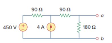
Figure 4.42
Expert Solution & Answer

Trending nowThis is a popular solution!

Students have asked these similar questions
please answer question below thx
please see image below to answer thx
Question 2: Answer C is wrong
Chapter 4 Solutions
EBK FUNDAMENTALS OF ELECTRIC CIRCUITS
Ch. 4.2 - Figure 4.3 For Practice Prob. 4.1. For the circuit...Ch. 4.2 - Figure 4.5 For Practice Prob. 4.2. Assume that Vo...Ch. 4.3 - Figure 4.8 Using the superposition theorem, find...Ch. 4.3 - Figure 4.11 Use superposition to find vx in the...Ch. 4.3 - Find I in the circuit of Fig. 4.14 using the...Ch. 4.4 - Find io in the circuit of Fig. 4.19 using source...Ch. 4.4 - Use source transformation to find ix in the...Ch. 4.5 - Using Thevenins theorem, find the equivalent...Ch. 4.5 - Find the Thevenin equivalent circuit of the...Ch. 4.5 - Obtain the Thevenin equivalent of the circuit in...
Ch. 4.6 - Find the Norton equivalent circuit for the circuit...Ch. 4.6 - Find the Norton equivalent circuit of the circuit...Ch. 4.8 - Determine the value of RL that will draw the...Ch. 4.9 - Rework Practice Prob. 4.9 using PSpice. Find the...Ch. 4.9 - Fin d the maximum power transferred to RL if the...Ch. 4.10 - The measured open-circuit voltage across a certain...Ch. 4.10 - Prob. 17PPCh. 4.10 - Obtain the current through the galvanometer,...Ch. 4 - The current through a branch in a linear network...Ch. 4 - For superposition, it is not required that only...Ch. 4 - The superposition principle applies to power...Ch. 4 - Refer to Fig. 4.67. The Thevenin resistance at...Ch. 4 - The Thevenin voltage across terminals a and b of...Ch. 4 - The Norton current at terminals a and b of the...Ch. 4 - The Norton resistance RN is exactly equal to the...Ch. 4 - Which pair of circuits in Fig. 4.68 are...Ch. 4 - A load is connected to a network. At the terminals...Ch. 4 - The source is supplying the maximum power to the...Ch. 4 - Calculate the current io in the circuit of Fig....Ch. 4 - Using Fig. 4.70, design a problem to help other...Ch. 4 - (a) In the circuit of Fig. 4.71, calculate vo and...Ch. 4 - Use linearity to determine io in the circuit of...Ch. 4 - For the circuit in Fig. 4.73, assume vo = 1 V, and...Ch. 4 - For the linear circuit shown in Fig. 4.74, use...Ch. 4 - Use linearity and the assumption that Vo = 1 V to...Ch. 4 - Using superposition, find Vo in the circuit of...Ch. 4 - Given that I = 6 amps when Vs = 160 volts and Is =...Ch. 4 - Using Fig. 4.78, design a problem to help other...Ch. 4 - Use the superposition principle to find io and vo...Ch. 4 - Determine vo in the circuit of Fig. 4.80 using the...Ch. 4 - Use superposition to find vo in the circuit of...Ch. 4 - Apply the superposition principle to find vo in...Ch. 4 - For the circuit in Fig. 4.83, use superposition to...Ch. 4 - Given the circuit in Fig. 4.84, use superposition...Ch. 4 - Use superposition to obtain vx in the circuit of...Ch. 4 - Use superposition to find Vo in the circuit of...Ch. 4 - Use superposition to solve for vx in the circuit...Ch. 4 - Use source transformation to reduce the circuit...Ch. 4 - Using Fig. 4.89, design a problem to help other...Ch. 4 - For the circuit in Fig, 4.90, use source...Ch. 4 - Referring to Fig. 4.91, use source transformation...Ch. 4 - Use source transformation to find the voltage Vx...Ch. 4 - Obtain vo in the circuit of Fig. 4.93 using source...Ch. 4 - Use source transformation to find io in the...Ch. 4 - Apply source transformation to find vx in the...Ch. 4 - Use source transformation to find Io in Fig. 4.96....Ch. 4 - Use source transformation to find vo in the...Ch. 4 - Use source transformation on the circuit shown in...Ch. 4 - Determine vx in the circuit of Fig. 4.99 using...Ch. 4 - Use source transformation to find ix in the...Ch. 4 - Determine the Thevenin equivalent circuit, shown...Ch. 4 - Using Fig. 4.102, design a problem that will help...Ch. 4 - Use Thevenins theorem to find vo in Prob. 4.12....Ch. 4 - Solve for the current i in the circuit of Fig....Ch. 4 - Find the Norton equivalent with respect to...Ch. 4 - Apply Thevenins theorem to find Vo in the circuit...Ch. 4 - Obtain the Thevenin equivalent at terminals a-b of...Ch. 4 - Find the Thevenin equivalent at terminals a-b of...Ch. 4 - Find the Thevenin and Norton equivalents at...Ch. 4 - For the circuit in Fig. 4.109, find the Thevenin...Ch. 4 - Find the Thevenin equivalent looking into...Ch. 4 - For the circuit in Fig. 4.111, obtain the Thevenin...Ch. 4 - Find the Thevenin equivalent of the circuit in...Ch. 4 - Using Fig. 4.113, design a problem to help other...Ch. 4 - Obtain the Thevenin and Norton equivalent circuits...Ch. 4 - Determine the Norton equivalent at terminals a-b...Ch. 4 - Find the Norton equivalent looking into terminals...Ch. 4 - Obtain the Norton equivalent of the circuit in...Ch. 4 - Given the circuit in Fig. 4.117, obtain the Norton...Ch. 4 - For the transistor model in Fig. 4.118, obtain the...Ch. 4 - Find the Norton equivalent at terminals a-b of the...Ch. 4 - Find the Thevenin equivalent between terminals a-b...Ch. 4 - Obtain the Norton equivalent at terminals a-b of...Ch. 4 - Use Nortons theorem to find Vo in the circuit of...Ch. 4 - Obtain the Thevenin and Norton equivalent circuits...Ch. 4 - The network in Fig. 4.124 models a bipolar...Ch. 4 - Determine the Thevenin and Norton equivalents at...Ch. 4 - For the circuit in Fig. 4.126, find the Thevenin...Ch. 4 - Obtain the Thevenin and Norton equivalent circuits...Ch. 4 - Find the Thevenin equivalent of the circuit in...Ch. 4 - Find the Norton equivalent for the circuit in Fig....Ch. 4 - Obtain the Thevenin equivalent seen at terminals...Ch. 4 - For the circuit shown in Fig. 4.131, determine the...Ch. 4 - Find the maximum power that can be delivered to...Ch. 4 - The variable resistor R in Fig. 4.133 is adjusted...Ch. 4 - Consider the 30- resistor in Fig. 4.134. First...Ch. 4 - Find the maximum power transferred to resistor R...Ch. 4 - Determine the maximum power delivered to the...Ch. 4 - For the circuit in Fig. 4.137, what resistor...Ch. 4 - (a) For the circuit in Fig. 4.138, obtain the...Ch. 4 - Determine the maximum power that can be delivered...Ch. 4 - For the bridge circuit shown in Fig. 4.140, find...Ch. 4 - For the circuit in Fig. 4.141, determine the value...Ch. 4 - Solve Prob. 4.34 using PSpice or MultiSim. Let V =...Ch. 4 - Use PSpice or MultiSim to solve Prob. 4.44. For...Ch. 4 - Use PSpice or MultiSim to solve Prob. 4.52.Ch. 4 - Obtain the Thevenin equivalent of the circuit in...Ch. 4 - Use PSpice or MultiSim to find the Thevenin...Ch. 4 - For the circuit in Fig. 4.126, use PSpice or...Ch. 4 - An automobile battery has an open circuit voltage...Ch. 4 - The following results were obtained from...Ch. 4 - When connected to a 4- resistor, a battery has a...Ch. 4 - The Thevenin equivalent at terminals a-b of the...Ch. 4 - A black box with a circuit in it is connected to a...Ch. 4 - A transducer is modeled with a current source Is...Ch. 4 - Consider the circuit in Fig. 4.144. An ammeter...Ch. 4 - Consider the circuit in Fig. 4.145. (a) Replace...Ch. 4 - The Wheatstone bridge circuit shown in Fig. 4.146...Ch. 4 - (a) In the Wheatstone bridge circuit of Fig. 4.147...Ch. 4 - Consider the bridge circuit of Fig. 4.148. Is the...Ch. 4 - The circuit in Fig. 4.149 models a common-emitter...Ch. 4 - An attenuator is an interface circuit that reduces...Ch. 4 - A dc voltmeter with a sensitivity of 10 k/V is...Ch. 4 - A resistance array is connected to a load resistor...Ch. 4 - A common-emitter amplifier circuit is shown in...Ch. 4 - For Practice Prob. 4.18, determine the current...
Knowledge Booster


Learn more about
Need a deep-dive on the concept behind this application? Look no further. Learn more about this topic, electrical-engineering and related others by exploring similar questions and additional content below.Similar questions
- please answer question and label accordinglyarrow_forwardQuestion 1: Answer A, 6EH is wrong Question 7: Answer D is wrongarrow_forwardA.With the aid of a diagram, describe fringing, and explain the impact that it has on the relevant magnetic circuit parameter. B. A coil of 1500 turns give rise to a magnetic flux of 2.5 mWb when carrying a certain current. If this current is reversed in 0.2 s, what is the average value of the e.m.f. induced in the coil? C.Define Mutual Inductance.Two coils are connected in series and their total inductance is measured as 0.12 H, and when the connection to one coil is reversed, the total inductance is measured as 0.04 H. If the coefficient of coupling is 0.8, determine:The self-inductance of each coil, and the mutual inductance between the coils.arrow_forward
- comparing Lenz's law and the left hand generator rule, which of these is the more important fundamental principle?arrow_forwardExample: Electric Field and Potential Inside a Charged Sphere Problem: A sphere of radius R = 0.2 m is uniformly charged with a total charge Q = 5 μC. The sphere is made of a dielectric material with relative permittivity € = 4. Calculate: 1. The electric field intensity E(r) inside and outside the sphere. 2. The electric potential (r) at any point inside the sphere. Solution: Step 1: Given Data Radius of the sphere: R = 0.2m, Total charge: Q-5 μC=5× 10° C. Step 2: Electric Field Inside the Sphere (< Using Gauss's Law:arrow_forwardplease remember to draw the circuitsarrow_forwardA balanced three-phase, A - connected induction motor consumes 3246 W when the l voltage is 208 V, and the line current is 10.6 A. Calculate: i. The motor's winding resistance. ii. The motor's winding reactance. 12 marrow_forwarda) An iron ring, having a mean circumference of 250 mm and a cross-sectional area of 400 mm², is wound with a coil of 70 turns. Using the following data, calculate the current required to set up a flux of 510µWb in the ring. H (A/m) 350 600 1250 B (T) 1.0 1.2 1.4 b) Calculate also: i. The inductance of the coil at the current obtained in Question 2 (a) above. ii. The self-induced e.m.f. if this current is switched off in 0.005 s. Assume that there is no residual flux.arrow_forwardA balanced three-phase, 1351-V, 60-Hz, A-connected source feeds a balanced Y- connected load with a per-phase impedance of 360 + j150 Q as shown in Figure 1. Calculate: i. The readings on each of the wattmeters ii. The power factor of the load using the wattmeter readings. NOTE: i. ii. Let VAN be the reference phasor, and the phase sequence be ABC anticlockwise. Assume the voltage-drop on the conductors between the source and the load to be zero volts. V b V₁ W 000 000 ; A 360 + j150 360 + j150 4 b 0000 000 B 360 + j150 C W₂ Figure 1arrow_forwarda) Three 30 2 resistors are arranged as shown in Figure 1 below. They are connected to a 480 V three-phase supply. The phase sequence is RYB anticlockwise. Calculate: i. The total power drawn by the circuit using the phase parameters. ii. The power read by each wattmeter. b) If Za, one of the 30 2 resistors, is now removed from the circuit, calculate: R- i. The line currents: IR, Iv, and la ii. The power read by each wattmeter. iii. The total power drawn by the two resistors. W₁ Be- W2 www 'R 22 12 B Figure 1arrow_forwardA certain magnetic circuit may be regarded as consisting of three parts, A, B and C in series, each one of which has a uniform cross-sectional area. Part A has a length of 300 mm and a cross- sectional area of 450 mm². Part B has a length of 120 mm and a cross-sectional area of 300 mm². Part C is an airgap 1.0 mm in length and of cross-sectional area 350 mm². The flux in the airgap is 0.35 mWb. Neglect magnetic leakage and fringing. The magnetic characteristic for parts A and B is given by: H (A/m) 400 560 800 1280 1800 B (T) 0.7 0.85 1.0 1.15 1.25 Calculate: i. The reluctance of each part, that is, of Part A, Part B, and Part C ii. The total reluctance of the magnetic circuit. iii. The total m.m.f.arrow_forwardHW_02.pdf EE 213-01 Assignments HW_#2 Toms are as muIcate uah.instructure.com b Answered: HW_#1 HW_01.pdf EE 213-01 Assignments P Pearson MyLab and Mastering uah.instructure.com P Course Home Watc... ✓ Download → Info × Close 1) (5 pts)For the circuit shown, find the value of Ia, Ib, Ic and Va: Ib 10 Ohms + Ic 40 Ohms 20 Ohms 70 Volts a Page 1 > of 2 - ZOOM + pui via Canvas Hint: use KCL to find Ic in terms of la and lb, use KVL around the right loop to find a relationship between la and lb, use KVL around the outer loop to solve for a current value (use ohms law for the voltage drops across the resistors) 2) (5 pts) – For problem 1, show that the power supplied (delivered) by the source equals the power absorbed by the resistors. 3) (5 pts) Determine the equivalent resistance looking into terminals a-b for the two circuits shown. Use series and parallel resistor combinations. Hint: work from the opposite end of terminals a-b towards terminals a-b a) 24 Ohms 10 Ohms 8 Ohms G a REQ b)…arrow_forwardarrow_back_iosSEE MORE QUESTIONSarrow_forward_ios
Recommended textbooks for you
 Introductory Circuit Analysis (13th Edition)Electrical EngineeringISBN:9780133923605Author:Robert L. BoylestadPublisher:PEARSON
 Delmar's Standard Textbook Of ElectricityElectrical EngineeringISBN:9781337900348Author:Stephen L. HermanPublisher:Cengage Learning
 Programmable Logic ControllersElectrical EngineeringISBN:9780073373843Author:Frank D. PetruzellaPublisher:McGraw-Hill Education
 Fundamentals of Electric CircuitsElectrical EngineeringISBN:9780078028229Author:Charles K Alexander, Matthew SadikuPublisher:McGraw-Hill Education
 Electric Circuits. (11th Edition)Electrical EngineeringISBN:9780134746968Author:James W. Nilsson, Susan RiedelPublisher:PEARSON
 Engineering ElectromagneticsElectrical EngineeringISBN:9780078028151Author:Hayt, William H. (william Hart), Jr, BUCK, John A.Publisher:Mcgraw-hill Education,
Introductory Circuit Analysis (13th Edition)
Electrical Engineering
ISBN:9780133923605
Author:Robert L. Boylestad
Publisher:PEARSON
Delmar's Standard Textbook Of Electricity
Electrical Engineering
ISBN:9781337900348
Author:Stephen L. Herman
Publisher:Cengage Learning
Programmable Logic Controllers
Electrical Engineering
ISBN:9780073373843
Author:Frank D. Petruzella
Publisher:McGraw-Hill Education
Fundamentals of Electric Circuits
Electrical Engineering
ISBN:9780078028229
Author:Charles K Alexander, Matthew Sadiku
Publisher:McGraw-Hill Education
Electric Circuits. (11th Edition)
Electrical Engineering
ISBN:9780134746968
Author:James W. Nilsson, Susan Riedel
Publisher:PEARSON
Engineering Electromagnetics
Electrical Engineering
ISBN:9780078028151
Author:Hayt, William H. (william Hart), Jr, BUCK, John A.
Publisher:Mcgraw-hill Education,
Norton's Theorem and Thevenin's Theorem - Electrical Circuit Analysis; Author: The Organic Chemistry Tutor;https://www.youtube.com/watch?v=-kkvqr1wSwA;License: Standard Youtube License