
Electrical Engineering: Principles & Applications (7th Edition)
7th Edition
ISBN: 9780134484143
Author: Allan R. Hambley
Publisher: PEARSON
expand_more
expand_more
format_list_bulleted
Concept explainers
Videos
Textbook Question
Chapter 4, Problem 4.33P
The circuit shown in Figure P4.33 is operating in steady state with the switch closed prior to t = 0. Find i(t) for t < 0 and for
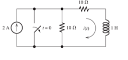
Figure P4.33
Expert Solution & Answer

Learn your wayIncludes step-by-step video

schedule05:45
Students have asked these similar questions
Question 2
A transistor is used as a switch and the waveforms are shown in Figure 2. The parameters are
Vcc = 225 V, VBE(sat) = 3 V, IB = 8 A, VCE(sat) = 2 V, Ics = 90 A, td = 0.5 µs, tr = 1 µs, ts = 3 µs, tƒ
= 2 μs, and f
10 kHz. The duty cycle is k 50%. The collector- emitter leakage current is
ICEO = 2 mA. Determine the power loss due to the collector current:
=
=
=
(a) during turn-on ton = td + tr
VCE
Vcc
(b) during conduction period tn
V CE(sat)
0
toff"
ton
Ics
0.9 Ics
(c) during turn-off toff = ts + tf
(d) during off-time tot
(e) the total average power losses PT
ICEO
0
IBS
0
Figure 2
V BE(sat)
0
主
*
td
tr
In
Is
If
to
iB
VBE
T= 1/fs
Question 1:
The beta (B) of the bipolar transistor shown in Figure 1 varies from 12 to 60. The load resistance
is Rc = 5. The dc supply voltage is VCC = 40 V and the input voltage to the base circuit is
VB = 5 V. If VCE(sat) = 1.2 V, VBE(sat) = 1.6 V, and RB = 0.8 2, calculate:
(a) the overdrive factor ODF.
(b) the forced ẞ
(c) the power loss in the transistor PT.
IB
VB
RB
+
V BE
RC
Vcc'
Ic
+
IE
Figure 1
VCE
I need help in creating a matlab code to find the currents
Chapter 4 Solutions
Electrical Engineering: Principles & Applications (7th Edition)
Ch. 4 - Suppose we have a capacitance C discharging...Ch. 4 - The dielectric materials used in real capacitors...Ch. 4 - The initial voltage across the capacitor shown in...Ch. 4 - A 100F capacitance is initially charged to 1000 V....Ch. 4 - At t = 0, a charged 10{ F capacitance is connected...Ch. 4 - At time t1 , a capacitance C is charged to a...Ch. 4 - Given an initially charged capacitance that begins...Ch. 4 - The initial voltage across the capacitor shown in...Ch. 4 - In physics, the half-life is often used to...Ch. 4 - We know that a 50F capacitance is charged to an...
Ch. 4 - We know that the capacitor shown in Figure P4.11...Ch. 4 - The purchasing power P of a certain unit of...Ch. 4 - Derive an expression for vC(t) in the circuit of...Ch. 4 - Suppose that at t= 0, we connect an uncharged 10 F...Ch. 4 - Suppose we have a capacitance C that is charged to...Ch. 4 - A person shuffling across a dry carpet can be...Ch. 4 - Prob. 4.17PCh. 4 - Consider the circuit shown in Figure P4.18. Prior...Ch. 4 - List the steps for dc steady-state analysis of RLC...Ch. 4 - Explain why we replace capacitances with open...Ch. 4 - Solve for the steady-state values of i1, i2, and...Ch. 4 - Consider the circuit shown in Figure P4.22. What...Ch. 4 - In the circuit of Figure P4.23, the switch is in...Ch. 4 - The circuit shown in Figure P4.24 has been set up...Ch. 4 - Solve for the steady-state values of i1 , i2, i3,...Ch. 4 - The circuit shown in Figure P4.26 is operating in...Ch. 4 - Prob. 4.27PCh. 4 - Consider the circuit of Figure P4.28 in which the...Ch. 4 - For the circuit shown in Figure P4.29, the switch...Ch. 4 - Consider the circuit of Figure P4.30 in which the...Ch. 4 - Give the expression for the time constant of a...Ch. 4 - A circuit consists of switches that open or close...Ch. 4 - The circuit shown in Figure P4.33 is operating in...Ch. 4 - Consider the circuit shown in Figure P4.34. The...Ch. 4 - Repeat Problem P4.34 given iL(0)=0A .Ch. 4 - Real inductors have series resistance associated...Ch. 4 - Determine expressions for and sketch is(t) to...Ch. 4 - For the circuit shown in Figure P4.38,, find an...Ch. 4 - The circuit shown in Figure P4.39 is operating in...Ch. 4 - Consider the circuit shown in Figure P4.40. A...Ch. 4 - Due to components not shown in the figure, the...Ch. 4 - The switch shown in Figure P4.42 has been closed...Ch. 4 - Determine expressions for and sketch vR(t) to...Ch. 4 - What are the steps in solving a circuit having a...Ch. 4 - Prob. 4.45PCh. 4 - Solve for vC(t) for t > 0 in the circuit of Figure...Ch. 4 - Solve for v(t) for t > 0 in the circuit of Figure...Ch. 4 - Prob. 4.48PCh. 4 - Consider the circuit shown inFigure P4.49. The...Ch. 4 - Consider the circuit shown in Figure P4.50. The...Ch. 4 - The voltage source shown in Figure P4.51 is called...Ch. 4 - Determine the form of the particular solution for...Ch. 4 - Determine the form of the particular solution for...Ch. 4 - Prob. 4.54PCh. 4 - Prob. 4.55PCh. 4 - How can first-or second-order circuits be...Ch. 4 - Prob. 4.57PCh. 4 - Prob. 4.58PCh. 4 - Prob. 4.59PCh. 4 - Sketch a step response for a second-order system...Ch. 4 - A dc source is connected to a series RLC circuit...Ch. 4 - Repeat Problem P4.61 for R = 40 .Ch. 4 - Repeat Problem P4.61 for R = 20 .Ch. 4 - Prob. 4.64PCh. 4 - Repeat Problem P4.64 for R=50 .Ch. 4 - Repeat Problem P4.64 for R=500 .Ch. 4 - Solve for i(t) for t > 0 in the circuit of Figure...Ch. 4 - Prob. 4.68PCh. 4 - Prob. 4.69PCh. 4 - Prob. 4.70PCh. 4 - Use MATLAB to derive an expression for vc(t)in the...Ch. 4 - Prob. 4.72PCh. 4 - Consider the circuit shown in FigureP4.50 in which...Ch. 4 - Prob. 4.74PCh. 4 - Prob. 4.75PCh. 4 - Use MATLAB to solve for the mesh currents in the...Ch. 4 - The switch m the circuit shown in Figure T4.1 is...Ch. 4 - Prob. 4.2PTCh. 4 - Consider the circuit shown in Figure T4.3. Figure...Ch. 4 - Consider the circuit shown in Figure T4.4 in which...Ch. 4 - Write the MATLAB commands to obtain the solution...
Additional Engineering Textbook Solutions
Find more solutions based on key concepts
The following is a multiplication problem in traditional base ten notation. Each letter represents a different ...
Computer Science: An Overview (13th Edition) (What's New in Computer Science)
If the block is held in the equilibrium position shown, determine the mass of the block at D.
INTERNATIONAL EDITION---Engineering Mechanics: Statics, 14th edition (SI unit)
Determine the maximum normal stress developed in the bar when it is subjected to a tension of P = 8kN.
Mechanics of Materials (10th Edition)
3.1 Discuss the differences between an error and a residual.
Elementary Surveying: An Introduction To Geomatics (15th Edition)
In the following exercises, write a program to carry out the task. The program should use variables for each of...
Introduction To Programming Using Visual Basic (11th Edition)
Distinguish among data definition commands, data manipulation commands, and data control commands.
Modern Database Management
Knowledge Booster


Learn more about
Need a deep-dive on the concept behind this application? Look no further. Learn more about this topic, electrical-engineering and related others by exploring similar questions and additional content below.Similar questions
- I need help fixing this MATLAB code: as I try to get it working there were some problems:arrow_forwardI need help in construct a matlab code to find the voltage of VR1 to VR4, the currents, and the watts based on that circuit.arrow_forwardQ2: Using D flip-flops, design a synchronous counter. The counter counts in the sequence 1,3,5,7, 1,7,5,3,1,3,5,7,.... when its enable input x is equal to 1; otherwise, the counter count 0.arrow_forward
- From the collector characteristic curves and the dc load line given below, determine the following: (a) Maximum collector current for linear operation (b) Base current at the maximum collector current (c) VCE at maximum collector current. lc (mA) 600 ΜΑ 60- 500 με 50- 400 με 40- 300 μ Α 30- Q-point 200 ΜΑ 20- 10- 100 μ Α 0 VCE (V) 1 2 3 4 5 6 7 8 9 10 [6 Paarrow_forwardProcedure:- 1- Connect the cct. shown in fig.(2). a ADDS DS Fig.(2) 2-For resistive load, measure le output voltage by using oscilloscope ;then sketch this wave. 3- Measure the average values ::f VL and IL: 4- Repeat steps 2 & 3 but for RL load. Report:- 1- Calculate the D.C. output vcl age theoretically and compare it with the test value. 2- Calculate the harmonic cont :nts of the load voltage, and explain how filter components may be selected. 3- Compare between the three-phase half & full-wave uncontrolled bridge rectifier. 4- Draw the waveform for the c:t. shown in fig.(2) but after replaced Di and D3 by thyristors with a 30° and a2 = 90° 5- Draw the waveform for the cct. shown in fig.(2) but after replace the 6-diodes by 6- thyristor. 6- Discuss your results. Please solve No. 4 and 5arrow_forwardPlease I want solution by handwrittenarrow_forward
- 8 00 ! Required information Consider the circuit given below. 0/2 points awarded 3 ΚΩ www t=0 6kM Scored R 1.5i Vc 1 μF 10 V If R = 5.00 kQ, determine vao+). The value of va(0) is 1.4545 V.arrow_forwardI want to know what does it look in a breadboard circuit, because I want to created it but I not sure it is build properly, can you give me an illustuation base on this image, it do need to real, something like virutal examplearrow_forwardCharge neutrality Since doped semiconductor remains electroneutral, the concentration of negative charges equals the concentration of positive charges. n+ Na,ionized p+Nd,ionized np = n; 2 2 N-Na N N d d р + 2 2 n = Nd-Na 2 + Na - 2 Na +n₁ 2 71/2 1/2 2 2 +n Concentration of electrons and holes 1. Calculate concentrations of electrons and holes at room temperature in Si and Ge with donor concentration of 1.5x10¹7 cm³ and acceptor concentration of 8x1016 cm-3. 2. Will these concentrations change much with the temperature increase to 100°C?arrow_forward
- Answer the questions on the end of the image pleasearrow_forwardAnswer these two questions on the end of the image, please 1.Calculate intrinsic carrier concentration for Si, Ge and GaAs at temperatures -20°C, 20°C (room temperature) and 120°C 2.Compare the obtained data with n and p shown on previous slide 25arrow_forwardCan you help me achieve the requirements using Arduino? I have encountered some issues with these requirements. Q.2: Suppose you have two push buttons connected to ports (0 & 1) and four LED's connected to ports (6-9). Write a program to flash ON the odd LED's if we press the switch 0 for 4s, flash ON the even LED's if we press the switch 1 for 5s and flash ON all the LED's otherwise for 6s.arrow_forward
arrow_back_ios
SEE MORE QUESTIONS
arrow_forward_ios
Recommended textbooks for you
 Introductory Circuit Analysis (13th Edition)Electrical EngineeringISBN:9780133923605Author:Robert L. BoylestadPublisher:PEARSON
 Delmar's Standard Textbook Of ElectricityElectrical EngineeringISBN:9781337900348Author:Stephen L. HermanPublisher:Cengage Learning
 Programmable Logic ControllersElectrical EngineeringISBN:9780073373843Author:Frank D. PetruzellaPublisher:McGraw-Hill Education
 Fundamentals of Electric CircuitsElectrical EngineeringISBN:9780078028229Author:Charles K Alexander, Matthew SadikuPublisher:McGraw-Hill Education
 Electric Circuits. (11th Edition)Electrical EngineeringISBN:9780134746968Author:James W. Nilsson, Susan RiedelPublisher:PEARSON
 Engineering ElectromagneticsElectrical EngineeringISBN:9780078028151Author:Hayt, William H. (william Hart), Jr, BUCK, John A.Publisher:Mcgraw-hill Education,
Introductory Circuit Analysis (13th Edition)
Electrical Engineering
ISBN:9780133923605
Author:Robert L. Boylestad
Publisher:PEARSON
Delmar's Standard Textbook Of Electricity
Electrical Engineering
ISBN:9781337900348
Author:Stephen L. Herman
Publisher:Cengage Learning
Programmable Logic Controllers
Electrical Engineering
ISBN:9780073373843
Author:Frank D. Petruzella
Publisher:McGraw-Hill Education
Fundamentals of Electric Circuits
Electrical Engineering
ISBN:9780078028229
Author:Charles K Alexander, Matthew Sadiku
Publisher:McGraw-Hill Education
Electric Circuits. (11th Edition)
Electrical Engineering
ISBN:9780134746968
Author:James W. Nilsson, Susan Riedel
Publisher:PEARSON
Engineering Electromagnetics
Electrical Engineering
ISBN:9780078028151
Author:Hayt, William H. (william Hart), Jr, BUCK, John A.
Publisher:Mcgraw-hill Education,
Capacitors Explained - The basics how capacitors work working principle; Author: The Engineering Mindset;https://www.youtube.com/watch?v=X4EUwTwZ110;License: Standard YouTube License, CC-BY