
Electrical Engineering: Principles & Applications (7th Edition)
7th Edition
ISBN: 9780134484143
Author: Allan R. Hambley
Publisher: PEARSON
expand_more
expand_more
format_list_bulleted
Videos
Textbook Question
Chapter 4, Problem 4.1PT
The switch m the circuit shown in Figure T4.1 is closed prior to t = 0. The switch opens at t = 0. Determine the time t, at which v(t) reaches 15V.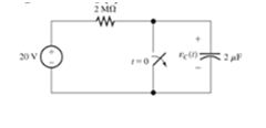
Figure T4.1
Expert Solution & Answer
Want to see the full answer?
Check out a sample textbook solution
Students have asked these similar questions
HW_#1
HW_01.pdf EE 213-01
Assignments
P Pearson MyLab and Mastering
uah.instructure.com
P Course Home
Watch out for units (i.e, kQ, mA, etc), show all units on answers and
clearly mark all answers
1)(5 pts) Specify if the following elements are absorbing or delivering power, and determine the
amount of power being absorbed or delivered.
10 V +
a)
5A
+
5 V
-
b)
2A
+ 10 V
-2A
2)(5 pts) Two circuits, shown by boxes A and B are connected as shown below. Use the
current reference direction provided and the voltage reference polarity shown to determine
the power for the interconnection. Also state the direction of power flow for the
connection: form A to B or B to A.
A
I
+
I
a) I = -6 A
V = -20 Volts
b) 1 = 8 A
V = 30 Volts
c) = 4 A
V = -80 Volts
d) I = -5 A
V = 40 Volts
B
3) (5 pts) Use Ohm's Law, KCL and KVL to determine values for V1, V2, V₁, I₁, and I2.
200 Ohms
A,
+
12
+
V1 75 Ohms
3 Amps
+
V2
300 Ohms
25 Ohms
4) (5 pts) For the circuit in Problem 2, determine the power (expressed as a…
Find the power delivered across the 10 ohm resistor
For the Circuit Below Find:
A) io in terms of Rb and the numerical resistor values provided in the schematic. Reduce your
solution to a minimal Equations
B)the power delivered across Rb in terms of Rb and the numerical resistor values provided in the
schematic. Reduce your solution to a minimal equation.
C) the power delivered across Rc if Rb is 5 Q
Ra $50
15Ω
M
120
90V
+1
Rb
150 150
m
Rc
Chapter 4 Solutions
Electrical Engineering: Principles & Applications (7th Edition)
Ch. 4 - Suppose we have a capacitance C discharging...Ch. 4 - The dielectric materials used in real capacitors...Ch. 4 - The initial voltage across the capacitor shown in...Ch. 4 - A 100F capacitance is initially charged to 1000 V....Ch. 4 - At t = 0, a charged 10{ F capacitance is connected...Ch. 4 - At time t1 , a capacitance C is charged to a...Ch. 4 - Given an initially charged capacitance that begins...Ch. 4 - The initial voltage across the capacitor shown in...Ch. 4 - In physics, the half-life is often used to...Ch. 4 - We know that a 50F capacitance is charged to an...
Ch. 4 - We know that the capacitor shown in Figure P4.11...Ch. 4 - The purchasing power P of a certain unit of...Ch. 4 - Derive an expression for vC(t) in the circuit of...Ch. 4 - Suppose that at t= 0, we connect an uncharged 10 F...Ch. 4 - Suppose we have a capacitance C that is charged to...Ch. 4 - A person shuffling across a dry carpet can be...Ch. 4 - Prob. 4.17PCh. 4 - Consider the circuit shown in Figure P4.18. Prior...Ch. 4 - List the steps for dc steady-state analysis of RLC...Ch. 4 - Explain why we replace capacitances with open...Ch. 4 - Solve for the steady-state values of i1, i2, and...Ch. 4 - Consider the circuit shown in Figure P4.22. What...Ch. 4 - In the circuit of Figure P4.23, the switch is in...Ch. 4 - The circuit shown in Figure P4.24 has been set up...Ch. 4 - Solve for the steady-state values of i1 , i2, i3,...Ch. 4 - The circuit shown in Figure P4.26 is operating in...Ch. 4 - Prob. 4.27PCh. 4 - Consider the circuit of Figure P4.28 in which the...Ch. 4 - For the circuit shown in Figure P4.29, the switch...Ch. 4 - Consider the circuit of Figure P4.30 in which the...Ch. 4 - Give the expression for the time constant of a...Ch. 4 - A circuit consists of switches that open or close...Ch. 4 - The circuit shown in Figure P4.33 is operating in...Ch. 4 - Consider the circuit shown in Figure P4.34. The...Ch. 4 - Repeat Problem P4.34 given iL(0)=0A .Ch. 4 - Real inductors have series resistance associated...Ch. 4 - Determine expressions for and sketch is(t) to...Ch. 4 - For the circuit shown in Figure P4.38,, find an...Ch. 4 - The circuit shown in Figure P4.39 is operating in...Ch. 4 - Consider the circuit shown in Figure P4.40. A...Ch. 4 - Due to components not shown in the figure, the...Ch. 4 - The switch shown in Figure P4.42 has been closed...Ch. 4 - Determine expressions for and sketch vR(t) to...Ch. 4 - What are the steps in solving a circuit having a...Ch. 4 - Prob. 4.45PCh. 4 - Solve for vC(t) for t > 0 in the circuit of Figure...Ch. 4 - Solve for v(t) for t > 0 in the circuit of Figure...Ch. 4 - Prob. 4.48PCh. 4 - Consider the circuit shown inFigure P4.49. The...Ch. 4 - Consider the circuit shown in Figure P4.50. The...Ch. 4 - The voltage source shown in Figure P4.51 is called...Ch. 4 - Determine the form of the particular solution for...Ch. 4 - Determine the form of the particular solution for...Ch. 4 - Prob. 4.54PCh. 4 - Prob. 4.55PCh. 4 - How can first-or second-order circuits be...Ch. 4 - Prob. 4.57PCh. 4 - Prob. 4.58PCh. 4 - Prob. 4.59PCh. 4 - Sketch a step response for a second-order system...Ch. 4 - A dc source is connected to a series RLC circuit...Ch. 4 - Repeat Problem P4.61 for R = 40 .Ch. 4 - Repeat Problem P4.61 for R = 20 .Ch. 4 - Prob. 4.64PCh. 4 - Repeat Problem P4.64 for R=50 .Ch. 4 - Repeat Problem P4.64 for R=500 .Ch. 4 - Solve for i(t) for t > 0 in the circuit of Figure...Ch. 4 - Prob. 4.68PCh. 4 - Prob. 4.69PCh. 4 - Prob. 4.70PCh. 4 - Use MATLAB to derive an expression for vc(t)in the...Ch. 4 - Prob. 4.72PCh. 4 - Consider the circuit shown in FigureP4.50 in which...Ch. 4 - Prob. 4.74PCh. 4 - Prob. 4.75PCh. 4 - Use MATLAB to solve for the mesh currents in the...Ch. 4 - The switch m the circuit shown in Figure T4.1 is...Ch. 4 - Prob. 4.2PTCh. 4 - Consider the circuit shown in Figure T4.3. Figure...Ch. 4 - Consider the circuit shown in Figure T4.4 in which...Ch. 4 - Write the MATLAB commands to obtain the solution...
Knowledge Booster


Learn more about
Need a deep-dive on the concept behind this application? Look no further. Learn more about this topic, electrical-engineering and related others by exploring similar questions and additional content below.Similar questions
- Problems A.1 The square-law modulator is a device for the generation of DSB-PC-AM signals. In the square-law modulator, the sum of the modulating signal and the carrier wave forms the input signal to a nonlinear device. The output signal of the nonlinear device is a linear combination of the input signal and the square of the input signal. The output signal of the nonlinear device is then band-pass filtered. The BPF has a center frequency that is the same as the carrier frequency and a bandwidth that is twice the message bandwidth. Show the output of the BPF is a DSB-PC-AM signal, and determine a requirement between the carrier frequency and the message bandwidth that must be satisfied.arrow_forwardGive the current voltage relationship of the D-MOSFET and E-MOSFET.arrow_forwardAnswer A is wrong.arrow_forward
- The part of machine level instruction, which tells the central processor what was to be done is: A. Address B. None of the above C. Operation code D. Operandarrow_forwardWhich of the following statement is TRUE? 1. In RISC processors, each instruction requires only two clock cycles to complete, resulting in consistent execution time 2. RISC has more transistors and fewer registers 3. RISC has more registers and fewer transistorsarrow_forwardDifferentiate between JFET and BJT.arrow_forward
- Give relation between αdc and βdc.arrow_forwardFind the power delivered across the 45 ohm resistorarrow_forwardA half-wave controlled rectifier is supplied by a 230 Vrms voltage source and has load resistance of 2502. Calculate the delay angle a that produces a load-absorbed power of 200W.arrow_forward
- not use ai pleasearrow_forwardFigure 1 shows a half-wave controlled rectifier which is supplied by a Vin = 120 Vrms voltage source. Assume that the load resistance is R = 10 2. Determine: a) The firing angle a of the thyristor to produce an average output voltage 50Vdc. Vin=Vmsinoot b) The average power Po absorbed by the load R. Figure 1 R = 1092arrow_forwardQ1. What is power dissipation in the Zener diode circuit given for a) RL=100 Ohm ? b) RL=∞arrow_forward
arrow_back_ios
SEE MORE QUESTIONS
arrow_forward_ios
Recommended textbooks for you
 Introductory Circuit Analysis (13th Edition)Electrical EngineeringISBN:9780133923605Author:Robert L. BoylestadPublisher:PEARSON
 Delmar's Standard Textbook Of ElectricityElectrical EngineeringISBN:9781337900348Author:Stephen L. HermanPublisher:Cengage Learning
 Programmable Logic ControllersElectrical EngineeringISBN:9780073373843Author:Frank D. PetruzellaPublisher:McGraw-Hill Education
 Fundamentals of Electric CircuitsElectrical EngineeringISBN:9780078028229Author:Charles K Alexander, Matthew SadikuPublisher:McGraw-Hill Education
 Electric Circuits. (11th Edition)Electrical EngineeringISBN:9780134746968Author:James W. Nilsson, Susan RiedelPublisher:PEARSON
 Engineering ElectromagneticsElectrical EngineeringISBN:9780078028151Author:Hayt, William H. (william Hart), Jr, BUCK, John A.Publisher:Mcgraw-hill Education,
Introductory Circuit Analysis (13th Edition)
Electrical Engineering
ISBN:9780133923605
Author:Robert L. Boylestad
Publisher:PEARSON
Delmar's Standard Textbook Of Electricity
Electrical Engineering
ISBN:9781337900348
Author:Stephen L. Herman
Publisher:Cengage Learning
Programmable Logic Controllers
Electrical Engineering
ISBN:9780073373843
Author:Frank D. Petruzella
Publisher:McGraw-Hill Education
Fundamentals of Electric Circuits
Electrical Engineering
ISBN:9780078028229
Author:Charles K Alexander, Matthew Sadiku
Publisher:McGraw-Hill Education
Electric Circuits. (11th Edition)
Electrical Engineering
ISBN:9780134746968
Author:James W. Nilsson, Susan Riedel
Publisher:PEARSON
Engineering Electromagnetics
Electrical Engineering
ISBN:9780078028151
Author:Hayt, William H. (william Hart), Jr, BUCK, John A.
Publisher:Mcgraw-hill Education,
ECE320 Lecture1-3c: Steady-State Error, System Type; Author: Rose-Hulman Online;https://www.youtube.com/watch?v=hG7dq-51AAg;License: Standard Youtube License