
Basic Engineering Circuit Analysis
11th Edition
ISBN: 9781118539293
Author: J. David Irwin, R. Mark Nelms
Publisher: WILEY
expand_more
expand_more
format_list_bulleted
Concept explainers
Videos
Textbook Question
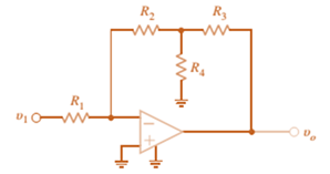
Chapter 4, Problem 42P
Find
Expert Solution & Answer
Want to see the full answer?
Check out a sample textbook solution
Students have asked these similar questions
Calculate the percent voltage regulation for a three-phase wye-connected 2500 kVA
6600-V turboalternator operating at full-load Unity power factor
The per
phase synchronous reactance and the armature resistance are 10.4 2 and 0.071 ≤2,
respectively?
Don't use ai to answer I will report you answer
Don't use ai to answer I will report you answer
Chapter 4 Solutions
Basic Engineering Circuit Analysis
Ch. 4 - An amplifier has a gain of 15 and the input...Ch. 4 - An amplifier has a gain of 5 and the output...Ch. 4 - An op-amp based amplifier has supply voltages of...Ch. 4 - For an ideal op-amp, the voltage gain and input...Ch. 4 - Revisit your answers in Problem 4.4 under the...Ch. 4 - Revisit the exact analysis of the inverting...Ch. 4 - Revisit the exact analysis of the inverting...Ch. 4 - An op-amp based amplifier has 18V supplies and a...Ch. 4 - Assuming an ideal op-amp, determine the voltage...Ch. 4 - Assuming an ideal op-amp, determine the voltage...
Ch. 4 - Assuming an ideal op-amp in Fig. P4.11, determine...Ch. 4 - Assuming an ideal op-amp, find the voltage gain of...Ch. 4 - Assuming an ideal op-amp in Fig. P4.13, determine...Ch. 4 - Determine the gain of the amplifier in Fig. P4.14....Ch. 4 - For the amplifier in Fig. P4.15, find the gain and...Ch. 4 - Using the ideal op-amp assumptions, determine the...Ch. 4 - Using the ideal op-amp assumptions, determine...Ch. 4 - In a useful application, the amplifier drives a...Ch. 4 - The op-amp in the amplifier in Fig. P4.19 operates...Ch. 4 - For the amplifier in Fig. P4.20, the maximum value...Ch. 4 - For the circuit in Fig. P4.21, (a) find Vo in...Ch. 4 - Find Vo in the circuit in Fig. P4.22, assuming...Ch. 4 - The network in Fig. P4.23 is a current-to-voltage...Ch. 4 - Prob. 24PCh. 4 - Determine the relationship between v1 and io in...Ch. 4 - Find Vo in the network in Fig. P4.26 and explain...Ch. 4 - Determine the expression for vo in the network in...Ch. 4 - Show that the output of the circuit in Fig. P4.28...Ch. 4 - Find vo in the network in Fig. P4.29.Ch. 4 - Find the voltage gain of the op-amp circuit shown...Ch. 4 - Determine the relationship between and in the...Ch. 4 - Prob. 32PCh. 4 - For the circuit in Fig. P4.33, find the value of...Ch. 4 - Find Vo in the circuit in Fig. P4.34.Ch. 4 - Find Vo in the circuit in Fig. P4.35.Ch. 4 - Determine the expression for the output voltage,...Ch. 4 - Determine the output voltage, of the noninverting...Ch. 4 - Find the input/output relationship for the current...Ch. 4 - Find V0 in the circuit in Fig. P4.39.Ch. 4 - Find Vo in the circuit in Fig. P4.40.Ch. 4 - Find the expression for in the differential...Ch. 4 - Find vo in the circuit in Fig. P4.42.Ch. 4 - Find the output voltage, vo, in the circuit in...Ch. 4 - The electronic ammeter in Example 4.7 has been...Ch. 4 - Given the summing amplifier shown in Fig. 4PFE-l,...Ch. 4 - Determine the output voltage V0 of the summing...Ch. 4 - What is the output voltage V0 in Fig. 4PFE-3. a....Ch. 4 - What value of Rf in the op-amp circuit of Fig....Ch. 4 - What is the voltage Vo in the circuit in Fig....
Additional Engineering Textbook Solutions
Find more solutions based on key concepts
7.13* For a bearing
DE = NUS 5 53’56 ”WT and angles to the right, compute the bearing of PG if angle
DEF 2 88°...
Elementary Surveying: An Introduction To Geomatics (15th Edition)
Write some Java statements that use the String methods indexOf and substring to find the first word in a string...
Java: An Introduction to Problem Solving and Programming (8th Edition)
What causes weld-induced residual stresses?
Degarmo's Materials And Processes In Manufacturing
15. The density of gasoline is 0.72 grams per cubic centimeter [g/cm3]. What is the mass in units of kilograms ...
Thinking Like an Engineer: An Active Learning Approach (4th Edition)
Answer question 3.33, but do not consider any pet having the breed of Unknown.
Database Concepts (8th Edition)
Find the no-load value of υo in the circuit shown.
Find υo when RL is 150 Ω.
How much power is dissipated in th...
Electric Circuits. (11th Edition)
Knowledge Booster


Learn more about
Need a deep-dive on the concept behind this application? Look no further. Learn more about this topic, electrical-engineering and related others by exploring similar questions and additional content below.Similar questions
- Don't use ai to answer I will report you answerarrow_forwardDon't use ai to answer I will report you answerarrow_forwardChose the correct answer: 1- A squirrel cage induction motor is not selected when (A) initial cost is the main consideration (B) maintenance cost is to be kept low (C) higher starting torque is the main consideration (D) all above considerations are involved 2- The torque of an induction motor is .............. (A) directly proportional to slip (B) inversely proportional to slip... (C) proportional to the square of the slip (D) none of the above 3- Insertion of resistance in the stator of an induction motor. (A) increases the load torque (B) decreases the starting torque (C) increases the starting torque (D) none of above tool to slip 10 or of the above 4- Increase in the length of air-gap in the induction motor results in the increasing of its (A) air-gap flux (B) magnetizing current (C) speed (D) power factor 5- In cumulatively cascade method for speed controlling, if PA is the number of poles of main motor and PB is the number of poles of auxiliary motor. Then the speed of the set…arrow_forward
- Chose the correct answer: 1- The resultant flux in stator winding of three-phase induction motor is equal to (A) Maximum value of flux due to any phase (B) Twice of the maximum value of flux due to any phase. (C) 0.5 times the maximum value of flux due to any phase (D) 1.5 times the maximum value of flux due to any phase 2- Which one of the following starters cannot be used for 3-phase, star - connected, slip-ring induction motor? (A) Auto-transformer starter (B) Star-delta starter (C) Direct-on-line starter (D) Rotor resistance starter 3- The crawling in the induction motor is caused by.............. (A) low voltage supply (B) high loads (D) improper design of the machine (C) harmonics developed in the motor 4- The 'cogging' of an induction motor can be avoided by........... (A) good ventilation (B) using DOL starter (C) star-connecting of stator winding (D) having number of rotor slots more or less than the number of stator slots 5- The method which can be used for the speed control…arrow_forwardManual solution only, no Al usedarrow_forwardChoose the correct answer: 1- The stator core of a 3- phase induction motor is laminated in order to reduce the Eddy current loss ) Weight of the stator (B) Hysteresis loss (C) Both eddy current and hysteresis loss - In cumulatively cascade method for speed controlling of a 3-phase induction motor, if PA is the number of poles of main motor and P, is the number of poles of auxiliary motor. Then the speed of the motor B is given by Ⓐ120f/ PA + PB CO (B) 120f/PA-Ps (C) 120f/PA (D) 120f/ Ps 3-Direct online starter is used for 3- phase induction motors having capacity COOOO ⑭Ⓐ Less than 5 h.p. (B) Less than 10 h.p. (C) Greater than 10 h.p. (D) For any capacity motor 4-Crawling of a 3- phase induction motor is a phenomena mainly associated with (B) 5th harmonics Ⓒ) 7 th harmonics (D) 2nd harmonics (A) 3rd harmonics 5-Cogging in a 3- phase induction motor is caused --------- (Ⓐ) If the number of stator slots are equal to number of rotor slots (B) If the motor is running at fraction of its…arrow_forward
- Choose the correct answer: 1-We avoid line starting of induction motor and use starter because... (A) It will run in reverse direction (B) It will pick up very high speed and may go out of step Motor takes five to seven times its full load current (D) Starting torque is very high 2-DOL starting of induction motors is usually restricted to........... A Low horsepower motors (D) High speed motors (B) Variable speed motors (C) High horsepower motors 3- The method which can be used for the speed control of induction motor from stator side is......... (A) V/f control (B) Controlling number of stator poles to control Ns (C) Adding rheostats in stator circuit All of these 4-In cumulatively cascade method for speed controlling, if PA is the number of poles of main motor and PB is the number of poles of auxiliary motor. Then the speed of the rotor B is given by 120f/PA + PB (B) 120f/PA-PB (C) 120f/PA 5-The crawling in the induction motor is caused by.............. (A) low voltage supply (B)…arrow_forwardFor the picture attached below the parameters are the following: f1 = 400 Hz m(t) = sin(2 fmt), where fm = 300 Hz. Assume ideal LPFs with a cut-o frequency of f1. What would be the value of frequency f2 be so that the carrier frequency is 2.5kHz? What modification of this system is required to generate USSB (at the same carrier frequency)? ( Note: this does not involbe changing the oscillator frequencies)arrow_forwardDetermine (analytically) the signals at points A-Garrow_forward
- Solve without using alarrow_forwardA Si step junction maintained at room temperature under equilibrium conditions has a p-side doping of NA 2X10¹⁵/cm³ and an n-side doping of ND=1015/cm³. Compare a) Vbi b) Xp, Xn, and W c) ɛ at x=0 d) V at x=0 Make sketches that are roughly to scale of the charge density, electric field, and electrostatic potential as a function of position.arrow_forwardCan you show how this answer was found?arrow_forward
arrow_back_ios
SEE MORE QUESTIONS
arrow_forward_ios
Recommended textbooks for you
 Introductory Circuit Analysis (13th Edition)Electrical EngineeringISBN:9780133923605Author:Robert L. BoylestadPublisher:PEARSON
 Delmar's Standard Textbook Of ElectricityElectrical EngineeringISBN:9781337900348Author:Stephen L. HermanPublisher:Cengage Learning
 Programmable Logic ControllersElectrical EngineeringISBN:9780073373843Author:Frank D. PetruzellaPublisher:McGraw-Hill Education
 Fundamentals of Electric CircuitsElectrical EngineeringISBN:9780078028229Author:Charles K Alexander, Matthew SadikuPublisher:McGraw-Hill Education
 Electric Circuits. (11th Edition)Electrical EngineeringISBN:9780134746968Author:James W. Nilsson, Susan RiedelPublisher:PEARSON
 Engineering ElectromagneticsElectrical EngineeringISBN:9780078028151Author:Hayt, William H. (william Hart), Jr, BUCK, John A.Publisher:Mcgraw-hill Education,
Introductory Circuit Analysis (13th Edition)
Electrical Engineering
ISBN:9780133923605
Author:Robert L. Boylestad
Publisher:PEARSON
Delmar's Standard Textbook Of Electricity
Electrical Engineering
ISBN:9781337900348
Author:Stephen L. Herman
Publisher:Cengage Learning
Programmable Logic Controllers
Electrical Engineering
ISBN:9780073373843
Author:Frank D. Petruzella
Publisher:McGraw-Hill Education
Fundamentals of Electric Circuits
Electrical Engineering
ISBN:9780078028229
Author:Charles K Alexander, Matthew Sadiku
Publisher:McGraw-Hill Education
Electric Circuits. (11th Edition)
Electrical Engineering
ISBN:9780134746968
Author:James W. Nilsson, Susan Riedel
Publisher:PEARSON
Engineering Electromagnetics
Electrical Engineering
ISBN:9780078028151
Author:Hayt, William H. (william Hart), Jr, BUCK, John A.
Publisher:Mcgraw-hill Education,
Nodal Analysis for Circuits Explained; Author: Engineer4Free;https://www.youtube.com/watch?v=f-sbANgw4fo;License: Standard Youtube License