
Basic Engineering Circuit Analysis
11th Edition
ISBN: 9781118539293
Author: J. David Irwin, R. Mark Nelms
Publisher: WILEY
expand_more
expand_more
format_list_bulleted
Concept explainers
Videos
Textbook Question
Chapter 4, Problem 14P
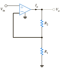
Determine the gain of the amplifier in Fig. P4.14. What is the value of
Expert Solution & Answer
Want to see the full answer?
Check out a sample textbook solution
Students have asked these similar questions
Q1/Sketch the root locus for the system shown in Figure 1 and find the following:
a. The exact point and gain where the locus crosses the jo-axis b. The breakaway point
on the real axis c. The range of K within which the system is stable d. Angles of
departure and arrival
R(s) +
K(s²-4s +20)
C(s)
(s+2)(s + 4)
Exam2
Subject: (Numerical Analysis)
Class: Third
Date: 27/4/2025
Time: 60 minutes
Q1. For what values of k does this system of equations has no solution? (use Gauss-Jordan eliminations)
kx + y + z = 1
x+ky + z = 1
x+y+kz=1
Consider the Difference equation of a causal Linear time-invariant (LTI) system given
by: (y(n) - 1.5y(n - 1) + 0.5y(n = 2) = x(n)
a) Implement the difference equation model of this system.
b) Find the system transfer function H(z).
c) For an input x(n) = 8(n), determine the output response y(n).
d) Verify the initial value theorem y(0) with part (c).
Chapter 4 Solutions
Basic Engineering Circuit Analysis
Ch. 4 - An amplifier has a gain of 15 and the input...Ch. 4 - An amplifier has a gain of 5 and the output...Ch. 4 - An op-amp based amplifier has supply voltages of...Ch. 4 - For an ideal op-amp, the voltage gain and input...Ch. 4 - Revisit your answers in Problem 4.4 under the...Ch. 4 - Revisit the exact analysis of the inverting...Ch. 4 - Revisit the exact analysis of the inverting...Ch. 4 - An op-amp based amplifier has 18V supplies and a...Ch. 4 - Assuming an ideal op-amp, determine the voltage...Ch. 4 - Assuming an ideal op-amp, determine the voltage...
Ch. 4 - Assuming an ideal op-amp in Fig. P4.11, determine...Ch. 4 - Assuming an ideal op-amp, find the voltage gain of...Ch. 4 - Assuming an ideal op-amp in Fig. P4.13, determine...Ch. 4 - Determine the gain of the amplifier in Fig. P4.14....Ch. 4 - For the amplifier in Fig. P4.15, find the gain and...Ch. 4 - Using the ideal op-amp assumptions, determine the...Ch. 4 - Using the ideal op-amp assumptions, determine...Ch. 4 - In a useful application, the amplifier drives a...Ch. 4 - The op-amp in the amplifier in Fig. P4.19 operates...Ch. 4 - For the amplifier in Fig. P4.20, the maximum value...Ch. 4 - For the circuit in Fig. P4.21, (a) find Vo in...Ch. 4 - Find Vo in the circuit in Fig. P4.22, assuming...Ch. 4 - The network in Fig. P4.23 is a current-to-voltage...Ch. 4 - Prob. 24PCh. 4 - Determine the relationship between v1 and io in...Ch. 4 - Find Vo in the network in Fig. P4.26 and explain...Ch. 4 - Determine the expression for vo in the network in...Ch. 4 - Show that the output of the circuit in Fig. P4.28...Ch. 4 - Find vo in the network in Fig. P4.29.Ch. 4 - Find the voltage gain of the op-amp circuit shown...Ch. 4 - Determine the relationship between and in the...Ch. 4 - Prob. 32PCh. 4 - For the circuit in Fig. P4.33, find the value of...Ch. 4 - Find Vo in the circuit in Fig. P4.34.Ch. 4 - Find Vo in the circuit in Fig. P4.35.Ch. 4 - Determine the expression for the output voltage,...Ch. 4 - Determine the output voltage, of the noninverting...Ch. 4 - Find the input/output relationship for the current...Ch. 4 - Find V0 in the circuit in Fig. P4.39.Ch. 4 - Find Vo in the circuit in Fig. P4.40.Ch. 4 - Find the expression for in the differential...Ch. 4 - Find vo in the circuit in Fig. P4.42.Ch. 4 - Find the output voltage, vo, in the circuit in...Ch. 4 - The electronic ammeter in Example 4.7 has been...Ch. 4 - Given the summing amplifier shown in Fig. 4PFE-l,...Ch. 4 - Determine the output voltage V0 of the summing...Ch. 4 - What is the output voltage V0 in Fig. 4PFE-3. a....Ch. 4 - What value of Rf in the op-amp circuit of Fig....Ch. 4 - What is the voltage Vo in the circuit in Fig....
Knowledge Booster


Learn more about
Need a deep-dive on the concept behind this application? Look no further. Learn more about this topic, electrical-engineering and related others by exploring similar questions and additional content below.Similar questions
- Q5B. Find the type of the controller in the following figures and use real values to find the transfer function of three of them[ Hint Pi,Pd and Lead,lag are found so put the controller with its corresponding compensator]. R₁ R₂ Rz HE C2 RA HE R₁ R2 RA とarrow_forwardQ1// Sketch the root locus for the unity feedback system. Where G(s)=)= K S3+252 +25 and find the following a. Sketch the asymptotes b. The exact point and gain where the locus crosses the jo-axis c. The breakaway point on the real axis d. The range of K within which the system is stable e. Angles of departure and arrival.arrow_forwardDetermine X(w) for the given function shown in Figure (1) by applying the differentiation property of the Fourier Transform. Figure (1) -1 x(t)arrow_forward
- Can you solve a question with a drawing Determine X(w) for the given function shown in Figure (1) by applying the differentiation property of the Fourier Transform. Figure (1) -1 x(t)arrow_forwardAn inductor has a current flow of 3 A when connected to a 240 V, 60 Hz power line. The inductor has a wire resistance of 15 Find the Q of the inductorarrow_forwardصورة من s94850121arrow_forward
- The joint density function of two continuous random variables X and Yis: p(x, y) = {Keós (x + y) Find (i) the constant K 0 2 0arrow_forwardShow all the steps please, Solve for the current through R2 if E2 is replaced by a current source of 10mA using superposition theorem. R5=470Ω R2=1000Ω R6=820Ωarrow_forwardPlease solve it by explaining the steps. I am trying to prepare for my exam tomorrow, so any tips and tricks to solve similar problems are highly appreciated. Plus, this is a past exam I am using to prepare.arrow_forwardPlease solve it by explaining the steps. I am trying to prepare for my exam today, so any tips and tricks to solve similar problems are highly appreciated. Plus, this is a past exam I am using to prepare.arrow_forwardIf C is the circle |z|=4 evaluate f f (z)dz for each of the following functions using residue. 1 f(z) = z(z²+6z+4)arrow_forwardIf C is the circle |z|=4 evaluate ff(z)dz for each of the following functions using residue. f(z) z(z²+6z+4)arrow_forwardarrow_back_iosSEE MORE QUESTIONSarrow_forward_ios
Recommended textbooks for you
 Introductory Circuit Analysis (13th Edition)Electrical EngineeringISBN:9780133923605Author:Robert L. BoylestadPublisher:PEARSON
 Delmar's Standard Textbook Of ElectricityElectrical EngineeringISBN:9781337900348Author:Stephen L. HermanPublisher:Cengage Learning
 Programmable Logic ControllersElectrical EngineeringISBN:9780073373843Author:Frank D. PetruzellaPublisher:McGraw-Hill Education
 Fundamentals of Electric CircuitsElectrical EngineeringISBN:9780078028229Author:Charles K Alexander, Matthew SadikuPublisher:McGraw-Hill Education
 Electric Circuits. (11th Edition)Electrical EngineeringISBN:9780134746968Author:James W. Nilsson, Susan RiedelPublisher:PEARSON
 Engineering ElectromagneticsElectrical EngineeringISBN:9780078028151Author:Hayt, William H. (william Hart), Jr, BUCK, John A.Publisher:Mcgraw-hill Education,
Introductory Circuit Analysis (13th Edition)
Electrical Engineering
ISBN:9780133923605
Author:Robert L. Boylestad
Publisher:PEARSON
Delmar's Standard Textbook Of Electricity
Electrical Engineering
ISBN:9781337900348
Author:Stephen L. Herman
Publisher:Cengage Learning
Programmable Logic Controllers
Electrical Engineering
ISBN:9780073373843
Author:Frank D. Petruzella
Publisher:McGraw-Hill Education
Fundamentals of Electric Circuits
Electrical Engineering
ISBN:9780078028229
Author:Charles K Alexander, Matthew Sadiku
Publisher:McGraw-Hill Education
Electric Circuits. (11th Edition)
Electrical Engineering
ISBN:9780134746968
Author:James W. Nilsson, Susan Riedel
Publisher:PEARSON
Engineering Electromagnetics
Electrical Engineering
ISBN:9780078028151
Author:Hayt, William H. (william Hart), Jr, BUCK, John A.
Publisher:Mcgraw-hill Education,
What is a Power Amplifier, And Do I Need One?; Author: Sweetwater;https://www.youtube.com/watch?v=2wkmSm4V00M;License: Standard Youtube License