
Basic Engineering Circuit Analysis
11th Edition
ISBN: 9781118539293
Author: J. David Irwin, R. Mark Nelms
Publisher: WILEY
expand_more
expand_more
format_list_bulleted
Concept explainers
Videos
Textbook Question
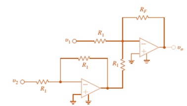
Chapter 4, Problem 41P
Find the expression for in the differential amplifier circuit shown in Fig. P4.41.
Expert Solution & Answer
Want to see the full answer?
Check out a sample textbook solution
Students have asked these similar questions
Need handwritten solution not using chatgpt Or AI
Solve by hand not using AI
Pls show neat and whole solution.
Chapter 4 Solutions
Basic Engineering Circuit Analysis
Ch. 4 - An amplifier has a gain of 15 and the input...Ch. 4 - An amplifier has a gain of 5 and the output...Ch. 4 - An op-amp based amplifier has supply voltages of...Ch. 4 - For an ideal op-amp, the voltage gain and input...Ch. 4 - Revisit your answers in Problem 4.4 under the...Ch. 4 - Revisit the exact analysis of the inverting...Ch. 4 - Revisit the exact analysis of the inverting...Ch. 4 - An op-amp based amplifier has 18V supplies and a...Ch. 4 - Assuming an ideal op-amp, determine the voltage...Ch. 4 - Assuming an ideal op-amp, determine the voltage...
Ch. 4 - Assuming an ideal op-amp in Fig. P4.11, determine...Ch. 4 - Assuming an ideal op-amp, find the voltage gain of...Ch. 4 - Assuming an ideal op-amp in Fig. P4.13, determine...Ch. 4 - Determine the gain of the amplifier in Fig. P4.14....Ch. 4 - For the amplifier in Fig. P4.15, find the gain and...Ch. 4 - Using the ideal op-amp assumptions, determine the...Ch. 4 - Using the ideal op-amp assumptions, determine...Ch. 4 - In a useful application, the amplifier drives a...Ch. 4 - The op-amp in the amplifier in Fig. P4.19 operates...Ch. 4 - For the amplifier in Fig. P4.20, the maximum value...Ch. 4 - For the circuit in Fig. P4.21, (a) find Vo in...Ch. 4 - Find Vo in the circuit in Fig. P4.22, assuming...Ch. 4 - The network in Fig. P4.23 is a current-to-voltage...Ch. 4 - Prob. 24PCh. 4 - Determine the relationship between v1 and io in...Ch. 4 - Find Vo in the network in Fig. P4.26 and explain...Ch. 4 - Determine the expression for vo in the network in...Ch. 4 - Show that the output of the circuit in Fig. P4.28...Ch. 4 - Find vo in the network in Fig. P4.29.Ch. 4 - Find the voltage gain of the op-amp circuit shown...Ch. 4 - Determine the relationship between and in the...Ch. 4 - Prob. 32PCh. 4 - For the circuit in Fig. P4.33, find the value of...Ch. 4 - Find Vo in the circuit in Fig. P4.34.Ch. 4 - Find Vo in the circuit in Fig. P4.35.Ch. 4 - Determine the expression for the output voltage,...Ch. 4 - Determine the output voltage, of the noninverting...Ch. 4 - Find the input/output relationship for the current...Ch. 4 - Find V0 in the circuit in Fig. P4.39.Ch. 4 - Find Vo in the circuit in Fig. P4.40.Ch. 4 - Find the expression for in the differential...Ch. 4 - Find vo in the circuit in Fig. P4.42.Ch. 4 - Find the output voltage, vo, in the circuit in...Ch. 4 - The electronic ammeter in Example 4.7 has been...Ch. 4 - Given the summing amplifier shown in Fig. 4PFE-l,...Ch. 4 - Determine the output voltage V0 of the summing...Ch. 4 - What is the output voltage V0 in Fig. 4PFE-3. a....Ch. 4 - What value of Rf in the op-amp circuit of Fig....Ch. 4 - What is the voltage Vo in the circuit in Fig....
Knowledge Booster


Learn more about
Need a deep-dive on the concept behind this application? Look no further. Learn more about this topic, electrical-engineering and related others by exploring similar questions and additional content below.Similar questions
- . (35pts) For the circuit given below, let [VBE] = 0.7 V and ẞ=co. Find I, V1, V2, V3, V4, and V5. R-12 Kiloohms 6 Qz R2-3 kilo onnis +27V es -2.7V R₂arrow_forward1) A circuit is given as shown. (a) Find and label the circuit nodes. (6) Determine I, II, I₂ and V, I mm 22 +1 m 50 4 12 12v 2 ти + V ≤1652 50 mv Ми 60arrow_forwardHANDWRITTEN SOLUTION NOT USING CHATGPT PLEASEarrow_forward
- Design a full-wave rectifier power supply using a 9.52:1 transformer. Assume that the outlet is120 V rms @ 60 Hz. Further assume that the diode turn-on voltage V D(on) is 0.7 V. Pick the valueof CL such that vo has a maximum ripple of 1 V p-p . Solve for the average value of vo = Vo (notethat this may be greater than 12 V) and iD(ave) = ID.arrow_forwardLight-emitting diodes (LEDs) are diodes made with III-V compound semiconductor materials such as aluminum gallium arsenide (AlGaAs), aluminum indium gallium phosphide (AlInGaP) or indium gallium nitride (InGaN), instead of silicon. The LEDs emit light when the device is operated under forward bias. LEDs of different colors have different turn-on voltages VD(on). For example: VD(on) : Red: ~ 1.6 V Yellow: ~ 1.7 V Green: ~ 1.8 V Blue: ~ 2.8 V White: ~ 3.8 V (a) Model these five LEDs with a simplified piecewise linear model (b) A rule of thumb is that it takes about 1 mA of current to “light” an LED while ~ 10 mA is needed for it to appear bright. Use the piecewise linear model for the LEDs, for the over-voltage indicator circuit to the right, find the values of Vin which will cause D1 or D2 to light (i.e. when ID1 or ID2 exceeds 1 mA).arrow_forwardConsider a fixed and updated instrumentation amplifier (where two resistors are lumped into one resistor), analyze the circuit if a common voltage source (VICM) is connected to two inputs. A₁ R₂ + R₁ R₂, RA www www R₁ R₁ www A3 X R₁ R₂ www www R₁₂ + Vo RA A2 V2 O- + R₂ 12 R₁arrow_forward
- Show that the input impedance of a lossy transmission line of length L connected to a load impedance of Z is given by Z₁Cosh(yL) + ZoSinh(yL) Zin = Zo ZoCosh(YL) + Z₁Sihh(YL) ex Where Cosh(x) = and Sinh(x) = are the hyperbolic cosine and sine, respectively. 2 2arrow_forwardA sinusoidal source of V = 10 and Z = 50 - j40 is connected to a 60 lossless transmission line of length 100 m with ẞ = 0.25. What is the Thevenin's equivalent of this system seen looking into the load end of the transmission line?arrow_forward2. On a distortionless transmission line, the voltage wave is given by v(L,t) = 110e0.005L Cos(10³t + 2L) +55e-0.005L Cos(108t-2L) where L is the length of the transmission line as measured from the load. If Z = 30002, find a,ẞ, vp, and Zo.arrow_forward
- A 50 transmission line is to be connected to a 72 load through a 1/4 quarter wave matching transformer. (a) What must be the characteristic impedance of the transmission line that is used to form the quarter wave transformer? (b) If the frequency of operation is 7 MHz and the phase velocity through the quarter wave section is 2c/3, what is the length of the quarter wave section? You may assume the transmission line forming the quarter wave section is lossless.arrow_forwardWhat is the SWR on a transmission line if the forward power arriving at the load is 5W but only 4.6W is dissipated by the load?arrow_forwardPlease do not send the AI solution as it is full of errors. Solve the question yourself, please. Q- If you have a unipolar winding stepper motor, draw the driver and the control circuit. In subject (A stepper motor driver circuit and direction control using Arduino microcontroller)arrow_forward
arrow_back_ios
SEE MORE QUESTIONS
arrow_forward_ios
Recommended textbooks for you
 Introductory Circuit Analysis (13th Edition)Electrical EngineeringISBN:9780133923605Author:Robert L. BoylestadPublisher:PEARSON
 Delmar's Standard Textbook Of ElectricityElectrical EngineeringISBN:9781337900348Author:Stephen L. HermanPublisher:Cengage Learning
 Programmable Logic ControllersElectrical EngineeringISBN:9780073373843Author:Frank D. PetruzellaPublisher:McGraw-Hill Education
 Fundamentals of Electric CircuitsElectrical EngineeringISBN:9780078028229Author:Charles K Alexander, Matthew SadikuPublisher:McGraw-Hill Education
 Electric Circuits. (11th Edition)Electrical EngineeringISBN:9780134746968Author:James W. Nilsson, Susan RiedelPublisher:PEARSON
 Engineering ElectromagneticsElectrical EngineeringISBN:9780078028151Author:Hayt, William H. (william Hart), Jr, BUCK, John A.Publisher:Mcgraw-hill Education,
Introductory Circuit Analysis (13th Edition)
Electrical Engineering
ISBN:9780133923605
Author:Robert L. Boylestad
Publisher:PEARSON
Delmar's Standard Textbook Of Electricity
Electrical Engineering
ISBN:9781337900348
Author:Stephen L. Herman
Publisher:Cengage Learning
Programmable Logic Controllers
Electrical Engineering
ISBN:9780073373843
Author:Frank D. Petruzella
Publisher:McGraw-Hill Education
Fundamentals of Electric Circuits
Electrical Engineering
ISBN:9780078028229
Author:Charles K Alexander, Matthew Sadiku
Publisher:McGraw-Hill Education
Electric Circuits. (11th Edition)
Electrical Engineering
ISBN:9780134746968
Author:James W. Nilsson, Susan Riedel
Publisher:PEARSON
Engineering Electromagnetics
Electrical Engineering
ISBN:9780078028151
Author:Hayt, William H. (william Hart), Jr, BUCK, John A.
Publisher:Mcgraw-hill Education,
What is a Power Amplifier, And Do I Need One?; Author: Sweetwater;https://www.youtube.com/watch?v=2wkmSm4V00M;License: Standard Youtube License