
Basic Engineering Circuit Analysis
11th Edition
ISBN: 9781118539293
Author: J. David Irwin, R. Mark Nelms
Publisher: WILEY
expand_more
expand_more
format_list_bulleted
Concept explainers
Videos
Textbook Question
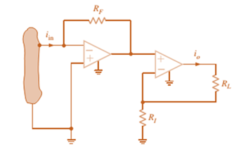
Chapter 4, Problem 38P
Find the input/output relationship for the current amplifier shown in Fig. P4.38.
Expert Solution & Answer
Want to see the full answer?
Check out a sample textbook solution
Students have asked these similar questions
ACS712
PV
Nov
ID
Voltage
RD
R1 sensing
VDS
R2
MOSFET S
VGS
Gate PWM
driver
Oscilloscope
Vpv, Ip
AO
Arduino
A1
Serial interface
01
Computer
Fig. 4. The proposed electronics load to measure PV characteristics.
explain the circuit and the curve
explain the circuit
Chapter 4 Solutions
Basic Engineering Circuit Analysis
Ch. 4 - An amplifier has a gain of 15 and the input...Ch. 4 - An amplifier has a gain of 5 and the output...Ch. 4 - An op-amp based amplifier has supply voltages of...Ch. 4 - For an ideal op-amp, the voltage gain and input...Ch. 4 - Revisit your answers in Problem 4.4 under the...Ch. 4 - Revisit the exact analysis of the inverting...Ch. 4 - Revisit the exact analysis of the inverting...Ch. 4 - An op-amp based amplifier has 18V supplies and a...Ch. 4 - Assuming an ideal op-amp, determine the voltage...Ch. 4 - Assuming an ideal op-amp, determine the voltage...
Ch. 4 - Assuming an ideal op-amp in Fig. P4.11, determine...Ch. 4 - Assuming an ideal op-amp, find the voltage gain of...Ch. 4 - Assuming an ideal op-amp in Fig. P4.13, determine...Ch. 4 - Determine the gain of the amplifier in Fig. P4.14....Ch. 4 - For the amplifier in Fig. P4.15, find the gain and...Ch. 4 - Using the ideal op-amp assumptions, determine the...Ch. 4 - Using the ideal op-amp assumptions, determine...Ch. 4 - In a useful application, the amplifier drives a...Ch. 4 - The op-amp in the amplifier in Fig. P4.19 operates...Ch. 4 - For the amplifier in Fig. P4.20, the maximum value...Ch. 4 - For the circuit in Fig. P4.21, (a) find Vo in...Ch. 4 - Find Vo in the circuit in Fig. P4.22, assuming...Ch. 4 - The network in Fig. P4.23 is a current-to-voltage...Ch. 4 - Prob. 24PCh. 4 - Determine the relationship between v1 and io in...Ch. 4 - Find Vo in the network in Fig. P4.26 and explain...Ch. 4 - Determine the expression for vo in the network in...Ch. 4 - Show that the output of the circuit in Fig. P4.28...Ch. 4 - Find vo in the network in Fig. P4.29.Ch. 4 - Find the voltage gain of the op-amp circuit shown...Ch. 4 - Determine the relationship between and in the...Ch. 4 - Prob. 32PCh. 4 - For the circuit in Fig. P4.33, find the value of...Ch. 4 - Find Vo in the circuit in Fig. P4.34.Ch. 4 - Find Vo in the circuit in Fig. P4.35.Ch. 4 - Determine the expression for the output voltage,...Ch. 4 - Determine the output voltage, of the noninverting...Ch. 4 - Find the input/output relationship for the current...Ch. 4 - Find V0 in the circuit in Fig. P4.39.Ch. 4 - Find Vo in the circuit in Fig. P4.40.Ch. 4 - Find the expression for in the differential...Ch. 4 - Find vo in the circuit in Fig. P4.42.Ch. 4 - Find the output voltage, vo, in the circuit in...Ch. 4 - The electronic ammeter in Example 4.7 has been...Ch. 4 - Given the summing amplifier shown in Fig. 4PFE-l,...Ch. 4 - Determine the output voltage V0 of the summing...Ch. 4 - What is the output voltage V0 in Fig. 4PFE-3. a....Ch. 4 - What value of Rf in the op-amp circuit of Fig....Ch. 4 - What is the voltage Vo in the circuit in Fig....
Knowledge Booster


Learn more about
Need a deep-dive on the concept behind this application? Look no further. Learn more about this topic, electrical-engineering and related others by exploring similar questions and additional content below.Similar questions
- Solve on paper not using chatgptarrow_forwardAssume that a building manager instructed you to install a water heater. The specs on the water heater nameplate reveals the following 240V, 2PH, 60HZ, 5.7KW. The manager insisted for the installation to be done with 10 AWG copper THWN-2 conductor, the length of run is 1200 FT away from the service panel. Calculate the voltage after the installation.arrow_forwardPlease confirm that my solution is correct, especially the block diagram. Please DRAW (not type) what the block diagram would look like if it's incorrect. thank youarrow_forward
- use this code on the bottom to answer the question in the photo clc; clearvars; % Read the file [y, Fs] = audioread('106miles.wav'); N = length(y); Nfft = 2^nextpow2(N); dt = 1/Fs; t = (0:dt:(N-1)*dt)'; % Ensure t is a column vector y = y - mean(y); % Remove DC component (if not already zero-mean) % Carrier signal (25 kHz) fc = 25000; % Carrier frequency in Hz carrier = cos(2 * pi * fc * t); % DSB-SC Modulation modulated_signal = y .* carrier; % Plot Time Domain Signal figure; subplot(2,1,1); plot(t, y); title('Original Signal (Time Domain)'); xlabel('Time (s)'); ylabel('Amplitude'); subplot(2,1,2); plot(t, modulated_signal); title('DSB-SC Modulated Signal (Time Domain)'); xlabel('Time (s)'); ylabel('Amplitude'); % Frequency Domain (FFT) Y = fft(y, Nfft) / Nfft; Modulated_Y = fft(modulated_signal, Nfft) / Nfft; f = Fs * (0:(Nfft/2)) / Nfft; % Frequency vector % Plot Frequency Domain Signal figure; subplot(2,1,1); plot(f, abs(Y(1:Nfft/2+1))); title('Original Signal…arrow_forward5-9 A 230 V shunt motor has a nominal arma- ture current of 60 A. If the armature resist- ance is 0.152, calculate the following: a. The counter-emf [V] b. The power supplied to the armature [W] c. The mechanical power developed by the motor, [kW] and [hp] 5-10 a. In Problem 5-9 calculate the initial start- ing current if the motor is directly con- nected across the 230 V line. b. Calculate the value of the starting resistor needed to limit the initial current to 115 A.arrow_forwardhow to solve this?arrow_forward
- For the circuit in Fig. P8.52, choose the load impedance ZLso that the power dissipated in it is a maximum. How much powerwill that be?arrow_forwardhow to solve the attached question? please explain or give reference where required in the solution.arrow_forwardHANDWRITTEN SOLUTION REQUIRED NOT USING CHATGPTarrow_forward
- Please only do part E and F. Please show your work and be as detailed as possible. Please explain the relationship between K the gain and stability of the system. Also, show how to plot the poles and why they are on either the real or imaginary axis. What is it about the example that indicated that? thank youarrow_forwardPlease draw the block diagram for this problem and explain how. thank youarrow_forwardPlease show your work and be as detailed as possible. I would like to really understand the connection between the type of loop, the dampness, and the gain, K. Thank youarrow_forward
arrow_back_ios
SEE MORE QUESTIONS
arrow_forward_ios
Recommended textbooks for you
 Introductory Circuit Analysis (13th Edition)Electrical EngineeringISBN:9780133923605Author:Robert L. BoylestadPublisher:PEARSON
 Delmar's Standard Textbook Of ElectricityElectrical EngineeringISBN:9781337900348Author:Stephen L. HermanPublisher:Cengage Learning
 Programmable Logic ControllersElectrical EngineeringISBN:9780073373843Author:Frank D. PetruzellaPublisher:McGraw-Hill Education
 Fundamentals of Electric CircuitsElectrical EngineeringISBN:9780078028229Author:Charles K Alexander, Matthew SadikuPublisher:McGraw-Hill Education
 Electric Circuits. (11th Edition)Electrical EngineeringISBN:9780134746968Author:James W. Nilsson, Susan RiedelPublisher:PEARSON
 Engineering ElectromagneticsElectrical EngineeringISBN:9780078028151Author:Hayt, William H. (william Hart), Jr, BUCK, John A.Publisher:Mcgraw-hill Education,
Introductory Circuit Analysis (13th Edition)
Electrical Engineering
ISBN:9780133923605
Author:Robert L. Boylestad
Publisher:PEARSON
Delmar's Standard Textbook Of Electricity
Electrical Engineering
ISBN:9781337900348
Author:Stephen L. Herman
Publisher:Cengage Learning
Programmable Logic Controllers
Electrical Engineering
ISBN:9780073373843
Author:Frank D. Petruzella
Publisher:McGraw-Hill Education
Fundamentals of Electric Circuits
Electrical Engineering
ISBN:9780078028229
Author:Charles K Alexander, Matthew Sadiku
Publisher:McGraw-Hill Education
Electric Circuits. (11th Edition)
Electrical Engineering
ISBN:9780134746968
Author:James W. Nilsson, Susan Riedel
Publisher:PEARSON
Engineering Electromagnetics
Electrical Engineering
ISBN:9780078028151
Author:Hayt, William H. (william Hart), Jr, BUCK, John A.
Publisher:Mcgraw-hill Education,
What is a Power Amplifier, And Do I Need One?; Author: Sweetwater;https://www.youtube.com/watch?v=2wkmSm4V00M;License: Standard Youtube License