Concept explainers
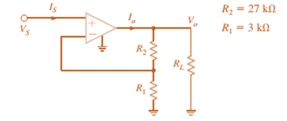
In a useful application, the amplifier drives a load. The circuit in Fig. P4.18 models this scenario.
(a) Sketch the gain
(b) Sketch
(c) Repeat (b) if
(d) What is the minimum value of
(e) What is the current

Want to see the full answer?
Check out a sample textbook solution
Chapter 4 Solutions
Basic Engineering Circuit Analysis
- 6) For each independent source in this circuit calculate the amount of power being supplied or the amount of power being absorbed + 6V www +3V- www 20 ми ми 352 0.5A + 3Varrow_forward2) A circuit is given as shown (a) Find and label circuit nodes. (b) Determine V, V₂, V₂, I₂ and I. + V₂ 452 m I2 6Ω www 52 t + V + 4A 노동 102 ww 1202 60 www I₂arrow_forwardA Darlington Pair consists of two transistors with the first BJT driving the base terminal of the second transistor as shown in the picture provided. What does the curve trace for a Darlington Pair of Bipolar Junction Transistors look like?arrow_forward
- Provide Pen and paper solution please not using AIarrow_forward5) If the current source supplies 448 watts, then what 15 the value of resistance R? ми R ↑ YA 62 ww 120 } ww 6_02 { wwarrow_forwardWhat is the equivalent resistance of this circuit between terminals A and B ? m 1852 A 7_A 122 도 www 50 ти B ww 36 Ω 201 www www 30√arrow_forward
- 3) A circuit is given as shown. (a) Find and label the circuit nodes. (6) Determine V2, V2, I₂, I₂ and Is © For each circuit element determine how much power it Supplies 15 absorbs. m 20 + 20 www 13 + 20 Z9V H 56 +1 LOV 1/2 1 4A + 3_22 3.2 ми + V₂ I 1arrow_forwardIn this experiment, we are going to use a 2N3904 BJT. Examine the data sheet for this device carefully. In particular, make a note of the current gain (identified by hFE). 1. Obtain the curve trace for a "Darlington Pair" of Bipolar Junction Transistors. A Darlington Pair consists of two transistors with the first BJT driving the base terminal of the second transistor as shown in Figure 1 below. A. Set up the primary sweep voltages for V1 the same as shown in the lecture notes (see the Darlington pair IV curve). B. Set up the secondary sweep currents for 11 to be an order of magnitude smaller than for the single BJT. In the Sweep Type box choose linear and enter the following 3 values: Start Value: 0, End Value: 8u and Increment: 1u (see lecture notes). C. Describe the primary differences you observe between the single BJT Curve Trace and that of the Darlington Pair. Discuss what might cause each difference. Q1 11 Q2 V1 Q2N3904 Figure 1. A Darlington Pair of 2N3904 transistors in a…arrow_forward2. Using the IV plots shown in Fig. 3 (and found in the reintroduction to PSpice) design a BJT biasing circuit that results in the following parameters: VCE = 2 Vand ig = 40 μA. We also require the power supply to be fixed at 5 Volts (this is where the load line intercepts the iB =ic = 0 line). You may use the circuit shown in Example 1. Note that all resistor values in Example 1 must be recalculated. Your solution for the base to ground and base to collector resistors may not be unique.arrow_forward
- A circuit is given as shown. (a) Find and label the circuit nodes. (6) Determine I, I₁, I2 and V₂ I₂ +1 I 12V ww 22 2 ти + 보통 162 - ти 4 52 12 50 602 I 1 Mwarrow_forwarda) A silicon wafer is uniformly doped p-type with NA=10¹³/cm³. At T=0K, what are the equilibrium hole and electron concentrations?arrow_forward1016 1015 Ge 101 Si 1013 1012 GaAs 10" (( uວ) uot¤ງແລ້ວuo ວາ.ຂ ວາsuuuT 0101 601 801 107 10% Determine the equilibrium electron and hole concentrations inside a uniformly doped sample of Si under the following conditions. (n; =1010/cm³ at 300K) a) T 300 K, NA << ND, ND = 1015/cm³ b) T 300 K, NA = 9X10¹⁵/cm³, ND = 1016/cm³ c) T = 450 K, NA = 0, ND = 1014/cm³ d) T = 650 K, NA = 0, ND = 1014/cm³ 10° 200 300 400 500 600 700 T(K)arrow_forward
 Introductory Circuit Analysis (13th Edition)Electrical EngineeringISBN:9780133923605Author:Robert L. BoylestadPublisher:PEARSON
 Delmar's Standard Textbook Of ElectricityElectrical EngineeringISBN:9781337900348Author:Stephen L. HermanPublisher:Cengage Learning
 Programmable Logic ControllersElectrical EngineeringISBN:9780073373843Author:Frank D. PetruzellaPublisher:McGraw-Hill Education
 Fundamentals of Electric CircuitsElectrical EngineeringISBN:9780078028229Author:Charles K Alexander, Matthew SadikuPublisher:McGraw-Hill Education
 Electric Circuits. (11th Edition)Electrical EngineeringISBN:9780134746968Author:James W. Nilsson, Susan RiedelPublisher:PEARSON
 Engineering ElectromagneticsElectrical EngineeringISBN:9780078028151Author:Hayt, William H. (william Hart), Jr, BUCK, John A.Publisher:Mcgraw-hill Education,


