
Videos
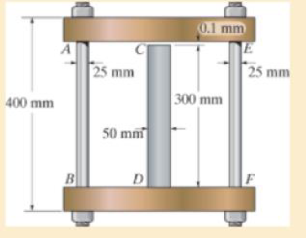
The assembly consists of two A992 steel bolts AB and EF and an 6061-T6 aluminum rod CD. When the temperature is at 30° C, the gap between the rod and rigid member AE is 0.1 mm Determine the normal stress developed in the bolts and the rod if the temperature rises to 130° C.
Assume BF is also rigid.
R4–1/2
The normal stress developed in the bolts and rod.
Answer to Problem 4.1RP
The normal stress developed in the bolts and rod are
Explanation of Solution
Given information:
The two bolts AB and EF are made of A992 steel.
The rod CD is made of 6061-T6 aluminum.
The Young’s modulus of the steel is
The Young’s modulus of the aluminum
The coefficient of thermal expansion of the steel
The coefficient of thermal expansion of the aluminum
The initial temperature
The finial temperature
The gap between the rod and rigid member AE is
The diameter of the bolts AB and EF
The diameter of the rod CD
The length of the bolts AB and EF
The length of the rod CD
Calculation:
Calculate the area of the bolts AB and EF
Substitute
Calculate the area of the rod CD
Substitute
Calculate the difference of temperature
Substitute
Show the free body diagram of the rigid cap as in Figure 1.
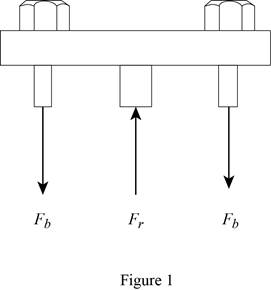
Refer Figure 1.
Calculate the vertical forces by applying the equation of equilibrium:
Sum of vertical forces is equal to 0.
Here,
Show the initial and final position of the assembly as in Figure 2.
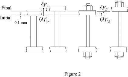
Refer Figure 2.
Here
The deformation is as follows:
Substitute
Calculate the force at the bolts AB and EF
Substitute
Calculate the force at the rod CD
Substitute
Calculate the normal stress developed in the bolts AB and EF
Substitute
Calculate the normal stress developed in the rod CD
Substitute
Hence, the normal stress developed in the bolts and rod are
Want to see more full solutions like this?
Chapter 4 Solutions
Mechanics of Materials (10th Edition)
Additional Engineering Textbook Solutions
Starting Out with Programming Logic and Design (5th Edition) (What's New in Computer Science)
Starting Out with Java: From Control Structures through Objects (7th Edition) (What's New in Computer Science)
Thermodynamics: An Engineering Approach
Starting Out with C++ from Control Structures to Objects (9th Edition)
Starting Out with Java: From Control Structures through Data Structures (4th Edition) (What's New in Computer Science)
Java: An Introduction to Problem Solving and Programming (8th Edition)


- I want the kinematic diagram to be draw like this plsarrow_forwardAccording to the principles and steps above, draw the kinematic diagram of following mechanisms. Mark the appropriate scale, calculates the degree of freedom. NO.1 NO.2 NO: 3 NO.: 4arrow_forwardAn office building is planned with a lateral-force-resisting system designed for earthquake resistance in aseismic zone. The seismic capacity of the proposed system, expressed as a force factor, is assumed tofollow a lognormal distribution with a median of 6.5 and a standard deviation of 1.5. The ground motionfrom the largest expected earthquake at the site is estimated to correspond to an equivalent force factor of 5.5.(a) What is the estimated probability that the building will experience damage when subjected to the largest expected earthquake? (b) If the building survives (i.e., experiences no damage) during a previous moderate earthquake with aforce factor of 4.0, what is the updated probability of failure of the building under the largest expectedearthquake?(c) Suppose future occurrences of the largest expected earthquake follow a Poisson process with a mean return period of 500 years. Assuming that damage events from different earthquakes are statisticallyindependent,…arrow_forward
- During a plant visit, it was noticed that a 12-m-long section of a 10-cm-diameter steam pipe is completely exposed to the ambient air. The temperature measurements indicate that the average temperature of the outer surface of the steam pipe is 75°C when the ambient temperature is 5°C. There are also light winds in the area at 10 km/h. The emissivity of the outer surface of the pipe is 0.8, and the average temperature of the surfaces surrounding the pipe, including the sky, is estimated to be 0°C. Determine the amount of heat lost from the steam during a 10-h-long work day. Steam is supplied by a gas-fired steam generator that has an efficiency of 80 percent, and the plant pays $1.05/therm of natural gas. If the pipe is insulated and 90 percent of the heat loss is saved, determine the amount of money this facility will save a year as a result of insulating the steam pipes. Assume the plant operates every day of the year for 10 h. State your assumptions.arrow_forwardAn old fashioned ice cream kit consists of two concentric cylinders of radii Ra and Rb. The inner cylinder is filled with milk and ice cream ingredients while the space between the two cylinders is filled with an ice-brine mixture. Ice cream begins to form on the inner surface of the inner cylinder. To expedite the process, would you recommend rotating the inner cylinder? Justify your recommendation. icecream/ ice-brine Ra Rbarrow_forwardFind temperatures STRICTLY USING RITZ APPROXIMATION METHODarrow_forward
- Solve this Problem using RITZ APPROXIMATION. STEP BY STEParrow_forwardB/40 The body is constructed of a uniform square plate, a uniform straight rod, a uniform quarter‐circular rod, and a particle (negligible dimensions). If each part has the indicated mass, determine the mass moments of inertia of the body about the x‐, y‐, and z‐axes. Answer Given.arrow_forward(read image) Answer:arrow_forward
- (read image) Answer Givenarrow_forwardB/16. The plane area shown in the top portion of the figure is rotated 180° about the x‐axis to form the body of revolution of mass m shown in the lower portion of the figure. Determine the mass moment of inertia of the body about the x‐axis. Answer Givenarrow_forward(read image) Answer:arrow_forward
 Elements Of ElectromagneticsMechanical EngineeringISBN:9780190698614Author:Sadiku, Matthew N. O.Publisher:Oxford University Press
 Mechanics of Materials (10th Edition)Mechanical EngineeringISBN:9780134319650Author:Russell C. HibbelerPublisher:PEARSON
 Thermodynamics: An Engineering ApproachMechanical EngineeringISBN:9781259822674Author:Yunus A. Cengel Dr., Michael A. BolesPublisher:McGraw-Hill Education
 Control Systems EngineeringMechanical EngineeringISBN:9781118170519Author:Norman S. NisePublisher:WILEY
 Mechanics of Materials (MindTap Course List)Mechanical EngineeringISBN:9781337093347Author:Barry J. Goodno, James M. GerePublisher:Cengage Learning
 Engineering Mechanics: StaticsMechanical EngineeringISBN:9781118807330Author:James L. Meriam, L. G. Kraige, J. N. BoltonPublisher:WILEY