What force is exerted on the tooth in Figure 4.38 if the tension in the wire is 25.0 N? Note that the force applied to the tooth is smaller than the tension in the wire, but this is necessitated by practical considerations of how force can be applied in the mouth. Explicitly show how you follow steps in the Problem-Solving Strategy for Newton's laws of motion. Figure 4.38 Braces are used to apply forces to teeth to realign them. Shown in this figure are the tensions applied by the wire to the protruding tooth. The total force applied to the tooth by the wire, F a p p , points straight toward the back of the mouth.
What force is exerted on the tooth in Figure 4.38 if the tension in the wire is 25.0 N? Note that the force applied to the tooth is smaller than the tension in the wire, but this is necessitated by practical considerations of how force can be applied in the mouth. Explicitly show how you follow steps in the Problem-Solving Strategy for Newton's laws of motion. Figure 4.38 Braces are used to apply forces to teeth to realign them. Shown in this figure are the tensions applied by the wire to the protruding tooth. The total force applied to the tooth by the wire, F a p p , points straight toward the back of the mouth.
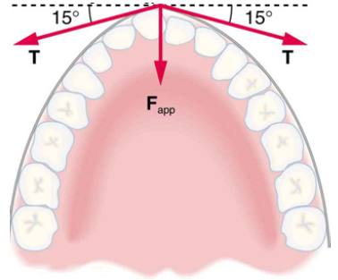
What force is exerted on the tooth in Figure 4.38 if the tension in the wire is 25.0 N? Note that the force applied to the tooth is smaller than the tension in the wire, but this is necessitated by practical considerations of how force can be applied in the mouth. Explicitly show how you follow steps in the Problem-Solving Strategy for Newton's laws of motion.
Figure 4.38 Braces are used to apply forces to teeth to realign them. Shown in this figure are the tensions applied by the wire to the protruding tooth. The total force applied to the tooth by the wire, Fapp, points straight toward the back of the mouth.
Three slits, each separated from its neighbor by d = 0.06 mm, are illuminated by a coherent light source of
wavelength 550 nm. The slits are extremely narrow. A screen is located L = 2.5 m from the slits. The
intensity on the centerline is 0.05 W. Consider a location on the screen x = 1.72 cm from the centerline.
a) Draw the phasors, according to the phasor model for the addition of harmonic waves, appropriate for this
location.
b) From the phasor diagram, calculate the intensity of light at this location.
A Jamin interferometer is a device for measuring or for comparing the indices of refraction of gases. A beam
of monochromatic light is split into two parts, each of which is directed along the axis of a separate cylindrical
tube before being recombined into a single beam that is viewed through a telescope. Suppose we are given the
following,
•
Length of each tube is L = 0.4 m.
• λ= 598 nm.
Both tubes are initially evacuated, and constructive interference is observed in the center of the field of view. As
air is slowly let into one of the tubes, the central field of view changes dark and back to bright a total of 198
times.
(a) What is the index of refraction for air?
(b) If the fringes can be counted to ±0.25 fringe, where one fringe is equivalent to one complete cycle of
intensity variation at the center of the field of view, to what accuracy can the index of refraction of air be
determined by this experiment?
1. An arrangement of three charges is shown below where q₁ = 1.6 × 10⁻¹⁹ C, q2 = -1.6×10⁻¹⁹ C,
and q3 3.2 x 10⁻¹⁹ C.
2 cm
Y
93
92
91
X
3 cm
(a) Calculate the magnitude and direction of the net force on q₁.
(b) Sketch the direction of the forces on qi
College Physics: A Strategic Approach (3rd Edition)
Knowledge Booster
Learn more about
Need a deep-dive on the concept behind this application? Look no further. Learn more about this topic, physics and related others by exploring similar questions and additional content below.


 Principles of Physics: A Calculus-Based TextPhysicsISBN:9781133104261Author:Raymond A. Serway, John W. JewettPublisher:Cengage Learning
 Glencoe Physics: Principles and Problems, Student...PhysicsISBN:9780078807213Author:Paul W. ZitzewitzPublisher:Glencoe/McGraw-Hill
 Physics for Scientists and Engineers: Foundations...PhysicsISBN:9781133939146Author:Katz, Debora M.Publisher:Cengage Learning
 University Physics Volume 1PhysicsISBN:9781938168277Author:William Moebs, Samuel J. Ling, Jeff SannyPublisher:OpenStax - Rice University
 An Introduction to Physical SciencePhysicsISBN:9781305079137Author:James Shipman, Jerry D. Wilson, Charles A. Higgins, Omar TorresPublisher:Cengage Learning
 College PhysicsPhysicsISBN:9781938168000Author:Paul Peter Urone, Roger HinrichsPublisher:OpenStax College