
(a)
The maximum factored load using Load and Resistance Factor Design (LRFD).
Answer to Problem 3.5.4P
The maximum factored load using LRFD is
Explanation of Solution
Given:
The following figure shows the A36 steel connection with
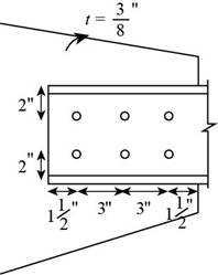
Figure-(1)
Concept Used:
Write the expression for the factored strength in yielding.
Write the expression for the factored strength in rupture.
Here, the factored yielding strength of the material is
Write the expression for block shear.
Write the expression for the upper limit of block shear.
Here, the upper limit is
Write the expression for the design block shear strength.
Here the design block shear strength, the minimum of Equation (III) and (IV), is
The maximum factored load is the minimum of Equation (I), (II), and (V).
Write the expression for the nominal strength in yielding for the tension member.
Here, the yield strength in yielding is
Write the expression for the nominal strength in rupture for the tension member.
Here, the yield strength in rupture is
Write the expression for the effective area.
Here, the area reduction factor is
Write the expression for the area reduction factor.
Here the distance from the centroid of the connected area
Write the expression for the net area of the tension member.
Here, the thickness of the tension member is
Write the expression for the diameter of the holes.
Here the diameter of the bolts is
Calculation:
Calculate the nominal shear strength of the tension member in yielding.
Substitute
Calculate the diameter of the holes.
Substitute
Calculate the net area of the tension member.
Substitute
Calculate the length of the connection.
Calculate the area reduction factor.
Substitute
Calculate the effective area of the member.
Substitute
Calculate the nominal shear strength of the tension member in rupture.
Substitute
Calculate the net area along the shear surface of the tension member.
Calculate the net area along the tension surface of the tension member.
Calculate the gross area along the shear surface in the gusset plate.
Calculate the net area along the shear surface of the gusset plate.
Substitute further.
Calculate the net area along the tension surface of the gusset plate.
Calculate the shear strength for the tension member.
Substitute
Calculate the upper limit.
Substitute
The value of the shear is larger than the upper limit. Hence, it is not feasible.
Adopt the shear strength of the tension member to be
Calculate the shear strength for the gusset plate.
Substitute
Calculate the upper limit
Substitute
The value of the shear is larger than the upper limit. Hence, it is not feasible.
Adopt the shear strength of the gusset plate to be
Compare the shear strength of the tension member and that of the gusset plate.
Thus the block shear strength is
Calculate the design block shear strength of the connection.
Calculate the factored yielding strength.
Substitute
Calculate the factored rupture strength.
Substitute
Calculate the factored strength of block shear.
Substitute
Conclusion:
Thus, the maximum factored load is
(b)
The allowable block shear strength of the connection.
Answer to Problem 3.5.4P
The allowable block shear strength of the connection is
Explanation of Solution
Concept used:
Write the expression for the factored design block shear strength.
Here the safety factor is
Calculation:
Calculate the allowable block shear strength of the connection.
Calculate the allowable yielding strength.
Substitute
Calculate the allowable rupture strength.
Substitute
Calculate the factored strength of block shear.
Substitute
Conclusion:
Thus, the maximum allowable block shear strength of the connection is
Want to see more full solutions like this?
Chapter 3 Solutions
Steel Design (Activate Learning with these NEW titles from Engineering!)

- What are the total earned work hours at completion for the column forms?arrow_forward6000 units have been installed to date with 9,000 units to install. Labor costs are $23,300.00 to date. What is the unit cost for labor to date?arrow_forwardThe base rate for labor is $15/hr. The labor burden is 35% and 3% for small tools for the labor. There are 1000 units to install. Records indicate that trade workers can install 10 units per hour, per trade worker. The owners need 15% overhead and profit to pay bills, pay interest on loan and provide some profit to the partners. What is the minimum bid assuming no risk avoidance factor?arrow_forward
- 5. (20 Points) Consider a channel width change in the same 7-foot wide rectangular in Problem 4. The horizontal channel narrows as depicted below. The flow rate is 90 cfs, and the energy loss (headloss) through the transition is 0.05 feet. The water depth at the entrance to the transition is initially 4'. 1 b₁ TOTAL ENERGY LINE V² 129 У1 I b₂ TOP VIEW 2 PROFILE VIEW h₁ = 0.05 EGL Y₂ = ? a) b) c) 2 Determine the width, b₂ that will cause a choke at location 2. Determine the water depth at the downstream end of the channel transition (y₂) section if b₂ = 5 feet. Calculate the change in water level after the transition. Plot the specific energy diagram showing all key points. Provide printout in homework. d) What will occur if b₂ = = 1.5 ft.?arrow_forward4. (20 Points) A transition section has been proposed to raise the bed level a height Dz in a 7-foot wide rectangular channel. The design flow rate in the channel is 90 cfs, and the energy loss (headloss) through the transition is 0.05 feet. The water depth at the entrance to the transition section is initially 4 feet. b₁ = b = b2 1 TOTAL ENERGY LINE V² 129 Ут TOP VIEW 2 hloss = 0.05 " EGL Y₂ = ? PROFILE VIEW a) Determine the minimum bed level rise, Dz, which will choke the flow. b) If the step height, Dz = 1 ft, determine the water depth (y2) at the downstream end of the channel transition section. Calculate the amount the water level drops or rises over the step. c) Plot the specific energy diagram showing all key points. Provide printout in Bework. d) What will occur if Dz = 3.0 ft.?. Crest Front Viewarrow_forward1. (20 Points) Determine the critical depth in the trapezoidal drainage ditch shown below. The slope of the ditch is 0.0016, the side slopes are 1V:2.5H, the bottom width is b = 14', and the design discharge is 500 cfs. At this discharge the depth is y = 4.25'. Also, determine the flow regime and calculate the Froude number. Ye= ? Z barrow_forward
- 3. (20 Points) A broad crested weir, 10 feet high, will be constructed in a rectangular channel B feet wide. The weir crest extends a length of B = 120 feet between the banks with 2 - 4 foot wide, round nosed piers in the channel. The width of the weir crest is 8 feet. If H = 6', determine the design discharge for the weir.arrow_forwardParking Needs vs. Alternative Transportation Methods for presentation slides include images and graphsarrow_forwardPlease explain step by step and show formulararrow_forward
 Steel Design (Activate Learning with these NEW ti...Civil EngineeringISBN:9781337094740Author:Segui, William T.Publisher:Cengage Learning
 Architectural Drafting and Design (MindTap Course...Civil EngineeringISBN:9781285165738Author:Alan Jefferis, David A. Madsen, David P. MadsenPublisher:Cengage Learning
 Materials Science And Engineering PropertiesCivil EngineeringISBN:9781111988609Author:Charles GilmorePublisher:Cengage Learning
 Construction Materials, Methods and Techniques (M...Civil EngineeringISBN:9781305086272Author:William P. Spence, Eva KultermannPublisher:Cengage Learning