
(a)
The section for loads given loads using load and resistance factor design (LRFD) method.
Answer to Problem 3.8.1P
The section for loads given loads using load and resistance factor design (LRFD) method is
Explanation of Solution
Given data:
Length of the connection is
Spacing of truss in the roof system is
Snow load is
Weight of roofing is
Section for the purlins is
Weight of the truss is
Calculation:
Calculate the snow load.
Calculate the load due to purlins.
Calculate the weight of the truss.
Calculate the slant height of the roof.
Calculate the weight of the roof.
Write the expression to calculate the total dead load.
Here, total dead load is
Substitute
Calculate the factored load using following load combination.
Here, factored load is
Substitute
Write the expression to calculate the exterior joint load.
Here, load on the exterior joint is
Substitute
Consider the free body diagram of the truss shown below.
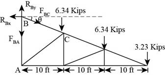
Figure-(1)
Write the expression to calculate the moment about point
Substitute
Solve further.
Consider joint
Write the expression for summation of forces acting in the horizontal direction.
Here, summation of all horizontal forces is
Substitute
Write the expression to calculate the required area.
Here, gross area is
Substitute
Write the expression to calculate the required area.
Here, effective area is
Substitute
Calculate the effective length of the truss.
Calculate the radius of gyration.
Substitute
Use section
Write the expression to calculate reduction factor.
Here, reduction factor is
Substitute
Write the expression to calculate the effective area for the section.
Substitute
Conclusion:
Since the gross area, net area and radius of gyration for this greater than the calculated value,
(b)
The section for loads given loads using allowable strength design (ASD) method.
Answer to Problem 3.8.1P
The section for loads given loads using allowable strength design (ASD) method is
Explanation of Solution
Given data:
Length of the connection is
Spacing of truss in the roof system is
Snow load is
Weight of roofing is
Section for the purlins is
Weight of the truss is
Calculation:
Calculate the ultimate load using the following load combination.
Here, ultimate load is
Substitute
Write the expression to calculate the exterior joint load.
Here, load on the exterior joint is
Substitute
Consider the free body of the truss as shown below.
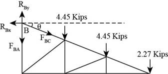
Figure-(2)
Write the expression to calculate the moment about point
Substitute
Solve further.
Consider joint
Write the expression for summation of forces acting in the horizontal direction.
Here, summation of all horizontal forces is
Substitute
Write the expression to calculate the required area.
Here, gross area is
Substitute
Write the expression to calculate the required area.
Here, effective area is
Substitute
Calculate the effective length of the truss.
Calculate the radius of gyration.
Substitute
Use section
Write the expression to calculate reduction factor.
Here, reduction factor is
Substitute
Write the expression to calculate the effective area for the section.
Substitute
Conclusion:
Since the gross area, net area and radius of gyration for this greater than the calculated value,
Want to see more full solutions like this?
Chapter 3 Solutions
Steel Design (Activate Learning with these NEW titles from Engineering!)

- nent 6-Transverse Shear & Deflection ↓ 2 of 2 -+ Automatic Zoom 4.) The built-up wooden beam shown is subjected to a vertical shear of 8 kN. Knowing the the nails are spaced longitudinally every 60 mm at A and every 25 mm at B, determine the shear force in the nails at A and B. (5 points) 50 300- 400 A 50 A C 150 B A 100 50 200 A B Dimensions in mm 5.) A 2.5 inch x 5.5 inch rectangular Southern pine section (E=1.8 x 10³ ksi) is used in an 8 ft cantilever span subjected to the loads shown. Compute the deflections at point A. (4 points) Дarrow_forwardE:/school%20pack/BENG%202/EG231/STATICS/LECTURE%20NOTES/PRACTICE%20QUESTIONS/EG%20231%20Chap-5%20Practice%20Que PDF 豆豆豆豆豆豆 aw V Aa | Ask Copilot - + 4 of 8 D 3. Calculate the y-coordinate of the centroid of the shaded area. 74 mm y 3232 mm mm DELL 32 mm -x F1 F2 F3 F4 F5 F6 F7 F8 F9 prt sc F10 home end F11 F 2 W E3 $ 4 € 95 % & 6 7 8 * 00 R T Y כ 9 O Parrow_forward*8-60. The 2-in.-diameter rod is subjected to the forces shown. Determine the state of stress at point B, and show the results on a differential element located at this point. Probs. 8-59/60 B 8 in. 600 lb 12 in. 500 lb 800 lbarrow_forward
- find SFD and BMD by using slope deflection methodarrow_forwardThe following relates to Problems 4 and 5. Christchurch, New Zealand experienced a major earthquake on February 22, 2011. It destroyed 100,000 homes. Data were collected on a sample of 300 damaged homes. These data are saved in the file called CIEG315 Homework 4 data.xlsx, which is available on Canvas under Files. A subset of the data is shown in the accompanying table. Two of the variables are qualitative in nature: Wall construction and roof construction. Two of the variables are quantitative: (1) Peak ground acceleration (PGA), a measure of the intensity of ground shaking that the home experienced in the earthquake (in units of acceleration of gravity, g); (2) Damage, which indicates the amount of damage experienced in the earthquake in New Zealand dollars; and (3) Building value, the pre-earthquake value of the home in New Zealand dollars. PGA (g) Damage (NZ$) Building Value (NZ$) Wall Construction Roof Construction Property ID 1 0.645 2 0.101 141,416 2,826 253,000 B 305,000 B T 3…arrow_forwardfind SFD and BMDarrow_forward
- The data needed to answer this question is given by this link: https://docs.google.com/spreadsheets/d/1vzb03U7Uvzm7X-by3OchQNwYeREzbP6Z-xzZMP2tzNw/edit?usp=sharing if it is easier to make a copy of the data because it is on view only then feel free to do so.arrow_forwardThe data needed to answer this question is given in the following link (file is on view only so if you would like to make a copy to make it easier for yourself feel free to do so) https://docs.google.com/spreadsheets/d/1aV5rsxdNjHnkeTkm5VqHzBXZgW-Ptbs3vqwk0SYiQPo/edit?usp=sharingarrow_forwardA k 000 6 ft A kips Bl D ft C C kips 10 ft 12 ft E B k/ft D E ft tarrow_forward
- H.W: show that the equations 1. (x+y)dy+(x-y)dx = 0 2. x²dy+(y²-xy)dx = 0 are homogeneous and solve:arrow_forwardH.W: Solve the differential equation y' - (1+x)(1 + y²) = 0arrow_forwardThe benchmark is 00.00. The backsights are 6.00, 9.32 and 13.75 and 14.00 The foresights are 6.00, 9.00 and 3.22. What is the height of the instrument? H.I. - 100.00 - 124.85 - 43.07- 24.85arrow_forward
 Steel Design (Activate Learning with these NEW ti...Civil EngineeringISBN:9781337094740Author:Segui, William T.Publisher:Cengage Learning