
Electrical Engineering: Principles & Applications (7th Edition)
7th Edition
ISBN: 9780134484143
Author: Allan R. Hambley
Publisher: PEARSON
expand_more
expand_more
format_list_bulleted
Videos
Textbook Question
Chapter 3, Problem 3.45P
The current flowing through a 2-H inductance is shown in Figure P3.45. Sketch the voltage. power, and stored energy versus time
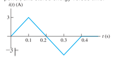
Figure P345
Expert Solution & Answer

Trending nowThis is a popular solution!

Students have asked these similar questions
A Darlington Pair consists of two transistors with the first BJT driving the base terminal of the second transistor as shown in the picture provided. What does the curve trace for a Darlington Pair of Bipolar Junction Transistors look like?
Provide Pen and paper solution please not using AI
5) If the current source supplies 448 watts, then what
15 the value of resistance R?
ми
R
↑ YA
62
ww
120 }
ww
6_02 {
ww
Chapter 3 Solutions
Electrical Engineering: Principles & Applications (7th Edition)
Ch. 3 - What is a dielectric material? Give two examples.Ch. 3 - Briefly discuss how current can flow “through” a...Ch. 3 - What current flows through an ideal capacitor if...Ch. 3 - Describe the internal construction of capacitors.Ch. 3 - A voltage of 50 V appears across a 10F capacitor....Ch. 3 - A 2000F capacitor, initially charged to 100V, is...Ch. 3 - A 5F Capacitor ischarged to 1000 V. Determine the...Ch. 3 - The voltage across a 10F capacitor is given by v...Ch. 3 - The voltage across a 1F capacitor is given by...Ch. 3 - Prior to t = 0, a 100F capacitance is uncharged...
Ch. 3 - The current through a 0.5F capacitor is shown in...Ch. 3 - Determine the capacitor voltage, power, and stored...Ch. 3 - A current given by i(t)=Imcos(t) flows through a...Ch. 3 - The current through a 3F capacitor is shown in...Ch. 3 - A constant (dc) current i(t)=3 mA flows into a 50F...Ch. 3 - The energy stored in a 2F capacitor is 200 J and...Ch. 3 - At t=t0 the voltage across a certain capacitance...Ch. 3 - An unusual capacitor has a capacitance that is a...Ch. 3 - For a resistor, what resistance corresponds to a...Ch. 3 - Suppose we have a very large capacitance (ideally,...Ch. 3 - We want to store sufficient energy in a 001-F...Ch. 3 - A 100F capacitor has a voltage given by v(t)=1010...Ch. 3 - How are capacitances combined in series and in...Ch. 3 - Find the equivalent capacitance for each of the...Ch. 3 - Find the equivalent capacitance between terminals...Ch. 3 - A network has a 5F capacitance in series with the...Ch. 3 - What are the minimum and maximum values of...Ch. 3 - Two initially uncharged capacitors C1=15F and...Ch. 3 - Suppose that we are designing a cardiac pacemaker...Ch. 3 - Suppose that we have two 100F capacitors One is...Ch. 3 - Determine the capacitance of a parallel-plate...Ch. 3 - A 100-pF capacitor is constructed of parallel...Ch. 3 - We have a parallel-plate capacitor with plates of...Ch. 3 - Suppose that we have a 1000-pF parallel-plate...Ch. 3 - Two 1F capacitors have an initial voltage of 100 V...Ch. 3 - Prob. 3.36PCh. 3 - Prob. 3.37PCh. 3 - A parallel-plate capacitor is used as a vibration...Ch. 3 - A 0.1F capacitor has a parasitic series resistance...Ch. 3 - Prob. 3.40PCh. 3 - Briefly discuss how inductors are constructed.Ch. 3 - The current flowing through an inductor is...Ch. 3 - If the current through an ideal inductor is...Ch. 3 - Briefly discuss the fluid-flow analogy for an...Ch. 3 - The current flowing through a 2-H inductance is...Ch. 3 - The current flowing through a 100-mH inductance is...Ch. 3 - The current flowing through a 2-H inductance is...Ch. 3 - The voltage across a 2-H inductance is shown in...Ch. 3 - The voltage across a 10 H inductance is given by...Ch. 3 - A 2-H inductance has i(0) = 0 and v(t)=texp(t) for...Ch. 3 - A constant voltage of 10V is applied to a 50H...Ch. 3 - At t = 0, the current flowing in a 05-H inductance...Ch. 3 - The current through a 100-mH inductance is given...Ch. 3 - Prior to t= 0, the current in a 2-H inductance is...Ch. 3 - At t= 0, a constant 5-V voltage source is applied...Ch. 3 - Prob. 3.56PCh. 3 - Al t= 5 s, the energy stored in a 2-H inductor is...Ch. 3 - What value of inductance (having zero initial...Ch. 3 - To what circuit element does a very large...Ch. 3 - The voltage across an inductance L is given by...Ch. 3 - Discuss how inductances are combined in series and...Ch. 3 - Determine the equivalent inductance for each of...Ch. 3 - Find the equivalent inductance for each of the...Ch. 3 - What is the maximum inductance that can be...Ch. 3 - Suppose we want to combine (in series or in...Ch. 3 - Prob. 3.66PCh. 3 - Two inductances L1=1H and L2=2H are connected in...Ch. 3 - A 10-mH inductor has a parasitic series resistance...Ch. 3 - Draw the equivalent circuit for a real inductor,...Ch. 3 - Suppose that the equivalent circuit shown in...Ch. 3 - Consider the circuit shown in Figure P3.71 in...Ch. 3 - The circuit shown in Figure P3.72 has...Ch. 3 - Describe briefly the physical basis for mutual...Ch. 3 - The mutually coupled inductances in Figure P3.74...Ch. 3 - Repeat Problem P3.74 with the dot placed at the...Ch. 3 - a. Derive an expression for the equivalent...Ch. 3 - Consider the parallel inductors shown in Figure...Ch. 3 - Consider the mutually coupled inductors shown in...Ch. 3 - Mutually coupled inductances have...Ch. 3 - The current through a 200-mH inductance is given...Ch. 3 - A 1-H inductance has iL(0)=0 and vL(t)=texp(t) for...Ch. 3 - The current flowing through a 10F capacitor having...Ch. 3 - Determine the equivalent capacitance Ceq for...Ch. 3 - A certain parallel-plate capacitor has plate...Ch. 3 - A 2-mH inductance has iab=0.3sin(2000t)A . Find an...Ch. 3 - Determine the equivalent inductance Leq between...Ch. 3 - Given that vc(t)=10sin(1000t)V , find vs(t)in the...Ch. 3 - Prob. 3.7PTCh. 3 - The current flowing through a 20F capacitor having...
Knowledge Booster


Learn more about
Need a deep-dive on the concept behind this application? Look no further. Learn more about this topic, electrical-engineering and related others by exploring similar questions and additional content below.Similar questions
- What is the equivalent resistance of this circuit between terminals A and B ? m 1852 A 7_A 122 도 www 50 ти B ww 36 Ω 201 www www 30√arrow_forward3) A circuit is given as shown. (a) Find and label the circuit nodes. (6) Determine V2, V2, I₂, I₂ and Is © For each circuit element determine how much power it Supplies 15 absorbs. m 20 + 20 www 13 + 20 Z9V H 56 +1 LOV 1/2 1 4A + 3_22 3.2 ми + V₂ I 1arrow_forwardIn this experiment, we are going to use a 2N3904 BJT. Examine the data sheet for this device carefully. In particular, make a note of the current gain (identified by hFE). 1. Obtain the curve trace for a "Darlington Pair" of Bipolar Junction Transistors. A Darlington Pair consists of two transistors with the first BJT driving the base terminal of the second transistor as shown in Figure 1 below. A. Set up the primary sweep voltages for V1 the same as shown in the lecture notes (see the Darlington pair IV curve). B. Set up the secondary sweep currents for 11 to be an order of magnitude smaller than for the single BJT. In the Sweep Type box choose linear and enter the following 3 values: Start Value: 0, End Value: 8u and Increment: 1u (see lecture notes). C. Describe the primary differences you observe between the single BJT Curve Trace and that of the Darlington Pair. Discuss what might cause each difference. Q1 11 Q2 V1 Q2N3904 Figure 1. A Darlington Pair of 2N3904 transistors in a…arrow_forward
- 2. Using the IV plots shown in Fig. 3 (and found in the reintroduction to PSpice) design a BJT biasing circuit that results in the following parameters: VCE = 2 Vand ig = 40 μA. We also require the power supply to be fixed at 5 Volts (this is where the load line intercepts the iB =ic = 0 line). You may use the circuit shown in Example 1. Note that all resistor values in Example 1 must be recalculated. Your solution for the base to ground and base to collector resistors may not be unique.arrow_forwardA circuit is given as shown. (a) Find and label the circuit nodes. (6) Determine I, I₁, I2 and V₂ I₂ +1 I 12V ww 22 2 ти + 보통 162 - ти 4 52 12 50 602 I 1 Mwarrow_forwarda) A silicon wafer is uniformly doped p-type with NA=10¹³/cm³. At T=0K, what are the equilibrium hole and electron concentrations?arrow_forward
- 1016 1015 Ge 101 Si 1013 1012 GaAs 10" (( uວ) uot¤ງແລ້ວuo ວາ.ຂ ວາsuuuT 0101 601 801 107 10% Determine the equilibrium electron and hole concentrations inside a uniformly doped sample of Si under the following conditions. (n; =1010/cm³ at 300K) a) T 300 K, NA << ND, ND = 1015/cm³ b) T 300 K, NA = 9X10¹⁵/cm³, ND = 1016/cm³ c) T = 450 K, NA = 0, ND = 1014/cm³ d) T = 650 K, NA = 0, ND = 1014/cm³ 10° 200 300 400 500 600 700 T(K)arrow_forwardb) A semiconductor is doped with an impurity concentration N such that N >> n; and all the impurities are ionized. Also, n = N and p = n2/N. Is the impurity a donor or an acceptor? Explain.arrow_forwardd) For a silicon sample maintained at T=300K, the Fermi level is located 0.259 eV above the intrinsic Fermi level. What are the hole and electron concentrations?arrow_forward
- e) In a nondegenerate germanium sample maintained under equilibrium conditions near room temperature, it is known that n=10¹³/cm³, n = 2p, and NA 0. Determine n and ND.arrow_forwardSolve fo the voltage across the 1kohm resistor using superposition for the three following cases: only V1 present, only V2 present, and both V1 and V2 present.arrow_forwardSemiconductor A has a band gap of 1eV, while semiconductor B has a band gap of 2eV. What is the ration of the intrinsic carrier concentrations in the two materials (n₁A/NB) at 300 K. Assume any differences in the carrier effective masses may be neglected.arrow_forward
arrow_back_ios
SEE MORE QUESTIONS
arrow_forward_ios
Recommended textbooks for you
 Introductory Circuit Analysis (13th Edition)Electrical EngineeringISBN:9780133923605Author:Robert L. BoylestadPublisher:PEARSON
 Delmar's Standard Textbook Of ElectricityElectrical EngineeringISBN:9781337900348Author:Stephen L. HermanPublisher:Cengage Learning
 Programmable Logic ControllersElectrical EngineeringISBN:9780073373843Author:Frank D. PetruzellaPublisher:McGraw-Hill Education
 Fundamentals of Electric CircuitsElectrical EngineeringISBN:9780078028229Author:Charles K Alexander, Matthew SadikuPublisher:McGraw-Hill Education
 Electric Circuits. (11th Edition)Electrical EngineeringISBN:9780134746968Author:James W. Nilsson, Susan RiedelPublisher:PEARSON
 Engineering ElectromagneticsElectrical EngineeringISBN:9780078028151Author:Hayt, William H. (william Hart), Jr, BUCK, John A.Publisher:Mcgraw-hill Education,
Introductory Circuit Analysis (13th Edition)
Electrical Engineering
ISBN:9780133923605
Author:Robert L. Boylestad
Publisher:PEARSON
Delmar's Standard Textbook Of Electricity
Electrical Engineering
ISBN:9781337900348
Author:Stephen L. Herman
Publisher:Cengage Learning
Programmable Logic Controllers
Electrical Engineering
ISBN:9780073373843
Author:Frank D. Petruzella
Publisher:McGraw-Hill Education
Fundamentals of Electric Circuits
Electrical Engineering
ISBN:9780078028229
Author:Charles K Alexander, Matthew Sadiku
Publisher:McGraw-Hill Education
Electric Circuits. (11th Edition)
Electrical Engineering
ISBN:9780134746968
Author:James W. Nilsson, Susan Riedel
Publisher:PEARSON
Engineering Electromagnetics
Electrical Engineering
ISBN:9780078028151
Author:Hayt, William H. (william Hart), Jr, BUCK, John A.
Publisher:Mcgraw-hill Education,
Inductors Explained - The basics how inductors work working principle; Author: The Engineering Mindset;https://www.youtube.com/watch?v=KSylo01n5FY;License: Standard Youtube License