
Electrical Engineering: Principles & Applications (7th Edition)
7th Edition
ISBN: 9780134484143
Author: Allan R. Hambley
Publisher: PEARSON
expand_more
expand_more
format_list_bulleted
Concept explainers
Videos
Textbook Question
Chapter 3, Problem 3.12P
Determine the capacitor voltage, power, and stored energy at t = 20 ms in the circuit ofFigure P3.12
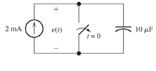
Figure P3.12
Expert Solution & Answer
Want to see the full answer?
Check out a sample textbook solution
Students have asked these similar questions
2-1) Lathi & Ding prob. 2.5-2 For the signals y(t) and x(t) shown below, find the component of the form
y(t) contained in x(t). In other words, find the optimum value of c in the approximation x(t) = cy(t) so that
the error signal energy is minimum. Also compute the error signal energy.
y(t)
x(t)
0
1
0
1
1. Is1 = 2ls2 = 4 × 10-16 A, B₁ = ẞ2 = 100, and R₁ = 5 kQ. Find the VB such that lx = 1 mA.
(30 points)
R1
ww
Q2
+
VB
Figure 1
2-2) Lathi & Ding prob. 2.6-1
2.6-1 Find the correlation coefficient p between of signal x(t) and each of the four pulses g1(1), 82(1),
83(1), and g4(f) shown in Fig. P2.6-1. To provide maximum margin against the noise along the
transmission path, which pair of pulses would you select for a binary communication?
Figure P.2.6-1
x(f)
(a)
8(1)
(b)
82(1)
(c)
1
1
sin 2πt
sin 4πt
-sin 2
0
0.707
83(1)
0
1
(d)
0
M
P
0.707
84(1)
(e)
0
0.5
-0.707
Chapter 3 Solutions
Electrical Engineering: Principles & Applications (7th Edition)
Ch. 3 - What is a dielectric material? Give two examples.Ch. 3 - Briefly discuss how current can flow “through” a...Ch. 3 - What current flows through an ideal capacitor if...Ch. 3 - Describe the internal construction of capacitors.Ch. 3 - A voltage of 50 V appears across a 10F capacitor....Ch. 3 - A 2000F capacitor, initially charged to 100V, is...Ch. 3 - A 5F Capacitor ischarged to 1000 V. Determine the...Ch. 3 - The voltage across a 10F capacitor is given by v...Ch. 3 - The voltage across a 1F capacitor is given by...Ch. 3 - Prior to t = 0, a 100F capacitance is uncharged...
Ch. 3 - The current through a 0.5F capacitor is shown in...Ch. 3 - Determine the capacitor voltage, power, and stored...Ch. 3 - A current given by i(t)=Imcos(t) flows through a...Ch. 3 - The current through a 3F capacitor is shown in...Ch. 3 - A constant (dc) current i(t)=3 mA flows into a 50F...Ch. 3 - The energy stored in a 2F capacitor is 200 J and...Ch. 3 - At t=t0 the voltage across a certain capacitance...Ch. 3 - An unusual capacitor has a capacitance that is a...Ch. 3 - For a resistor, what resistance corresponds to a...Ch. 3 - Suppose we have a very large capacitance (ideally,...Ch. 3 - We want to store sufficient energy in a 001-F...Ch. 3 - A 100F capacitor has a voltage given by v(t)=1010...Ch. 3 - How are capacitances combined in series and in...Ch. 3 - Find the equivalent capacitance for each of the...Ch. 3 - Find the equivalent capacitance between terminals...Ch. 3 - A network has a 5F capacitance in series with the...Ch. 3 - What are the minimum and maximum values of...Ch. 3 - Two initially uncharged capacitors C1=15F and...Ch. 3 - Suppose that we are designing a cardiac pacemaker...Ch. 3 - Suppose that we have two 100F capacitors One is...Ch. 3 - Determine the capacitance of a parallel-plate...Ch. 3 - A 100-pF capacitor is constructed of parallel...Ch. 3 - We have a parallel-plate capacitor with plates of...Ch. 3 - Suppose that we have a 1000-pF parallel-plate...Ch. 3 - Two 1F capacitors have an initial voltage of 100 V...Ch. 3 - Prob. 3.36PCh. 3 - Prob. 3.37PCh. 3 - A parallel-plate capacitor is used as a vibration...Ch. 3 - A 0.1F capacitor has a parasitic series resistance...Ch. 3 - Prob. 3.40PCh. 3 - Briefly discuss how inductors are constructed.Ch. 3 - The current flowing through an inductor is...Ch. 3 - If the current through an ideal inductor is...Ch. 3 - Briefly discuss the fluid-flow analogy for an...Ch. 3 - The current flowing through a 2-H inductance is...Ch. 3 - The current flowing through a 100-mH inductance is...Ch. 3 - The current flowing through a 2-H inductance is...Ch. 3 - The voltage across a 2-H inductance is shown in...Ch. 3 - The voltage across a 10 H inductance is given by...Ch. 3 - A 2-H inductance has i(0) = 0 and v(t)=texp(t) for...Ch. 3 - A constant voltage of 10V is applied to a 50H...Ch. 3 - At t = 0, the current flowing in a 05-H inductance...Ch. 3 - The current through a 100-mH inductance is given...Ch. 3 - Prior to t= 0, the current in a 2-H inductance is...Ch. 3 - At t= 0, a constant 5-V voltage source is applied...Ch. 3 - Prob. 3.56PCh. 3 - Al t= 5 s, the energy stored in a 2-H inductor is...Ch. 3 - What value of inductance (having zero initial...Ch. 3 - To what circuit element does a very large...Ch. 3 - The voltage across an inductance L is given by...Ch. 3 - Discuss how inductances are combined in series and...Ch. 3 - Determine the equivalent inductance for each of...Ch. 3 - Find the equivalent inductance for each of the...Ch. 3 - What is the maximum inductance that can be...Ch. 3 - Suppose we want to combine (in series or in...Ch. 3 - Prob. 3.66PCh. 3 - Two inductances L1=1H and L2=2H are connected in...Ch. 3 - A 10-mH inductor has a parasitic series resistance...Ch. 3 - Draw the equivalent circuit for a real inductor,...Ch. 3 - Suppose that the equivalent circuit shown in...Ch. 3 - Consider the circuit shown in Figure P3.71 in...Ch. 3 - The circuit shown in Figure P3.72 has...Ch. 3 - Describe briefly the physical basis for mutual...Ch. 3 - The mutually coupled inductances in Figure P3.74...Ch. 3 - Repeat Problem P3.74 with the dot placed at the...Ch. 3 - a. Derive an expression for the equivalent...Ch. 3 - Consider the parallel inductors shown in Figure...Ch. 3 - Consider the mutually coupled inductors shown in...Ch. 3 - Mutually coupled inductances have...Ch. 3 - The current through a 200-mH inductance is given...Ch. 3 - A 1-H inductance has iL(0)=0 and vL(t)=texp(t) for...Ch. 3 - The current flowing through a 10F capacitor having...Ch. 3 - Determine the equivalent capacitance Ceq for...Ch. 3 - A certain parallel-plate capacitor has plate...Ch. 3 - A 2-mH inductance has iab=0.3sin(2000t)A . Find an...Ch. 3 - Determine the equivalent inductance Leq between...Ch. 3 - Given that vc(t)=10sin(1000t)V , find vs(t)in the...Ch. 3 - Prob. 3.7PTCh. 3 - The current flowing through a 20F capacitor having...
Additional Engineering Textbook Solutions
Find more solutions based on key concepts
Explain the problems that denormalized tables may have for insert, update, and delete actions.
Database Concepts (8th Edition)
State whether each of the following is true or false. A set of statements contained within a pair of parenthese...
Java How to Program, Early Objects (11th Edition) (Deitel: How to Program)
What populates the Smalltalk world?
Concepts Of Programming Languages
Initials Write a program that gets a string containing a persons first, middle, and last names, and displays th...
Starting Out with Python (4th Edition)
List the five major hardware components of a computer system.
Starting Out With Visual Basic (8th Edition)
Knowledge Booster


Learn more about
Need a deep-dive on the concept behind this application? Look no further. Learn more about this topic, electrical-engineering and related others by exploring similar questions and additional content below.Similar questions
- 2. Determine the operation point and the small-signal model of Q₁ for each of the circuits shown in Fig. 2. Assume Is = 8 × 10-16 A, B = 100 and VA = ∞. a) 20 points b) 20 points 0.8 V RC 50 Ω + Vcc = 2.5 V 4A" Figure 2-a Rc1kQ + Vcc = 2.5 V Figure 2-barrow_forwardPlease explain in detail how to solve this question. Show detailed steps in terms of calculation and theory. thank youarrow_forwardPls show neat and whole solutionarrow_forward
- Pls show neat and whole solutionarrow_forwardPlease explain in detail how to solve this question. Include steps with calculations and theory. thank youarrow_forwardFinding crystallographic direction Z pt. 2 head pt. 1: ៩ Example 2: pt. 1 x₁ = a, y₁ = b/2, z₁ = 0 pt. 2 x2=-a, y₂ = b, Z₂ = c -a-a b-b/2 c-0 a b c tail => -2, 1/2, 1 Multiplying by 2 to eliminate the fraction -4,1,2 => [412] where the overbar represents a negative index families of directionsarrow_forward
- Crystallographic planes Crystallographic planes are denoted by Miller indices. 5b Algorithm for Miller indices 1. Read off intercepts of plane with axes in terms of a, b, c 2. Take reciprocals of intercepts 3. Reduce to smallest integer values 4. Enclose in parentheses, no commas. 353 1/3 1/5 1/3 535 (535) In the cubic system, a plane and a direction with the same indices are orthogonal. E.g. [100] direction is perpendicular to (100) plane. Correspondingly, [123] direction is perpendicular to (123) plane. [2,3,3] Plane intercepts axes at 3a, 2b, 2c 2 11 1 Reciprocal numbers are: 3'2'2 b. Indices of the plane (Miller): (2,3,3) 2 a Indices of the direction: [2,3,3] X (200) (100) (110) (111) (100) Indices of crystallographic plane can be found from cross product of indices of any two non-parallel directions in this plane.arrow_forwardCrystallographic positions Crystallographic position is denoted by three numbers, which are coefficients of the position vector, e.g. ½½½ for the red atom. Here the 'new' atom is at a/2 + b/2 + c/2 Silicon crystal has so-called "diamond type lattice". Each Si atom has 4 nearest neighbors. Diamond lattice starts with a FCC lattice and then adds four additional INTERNAL atoms at locations r = a/4+b/4+c/4 away from each of the atoms. In other words, diamond lattice is formed by two FCC lattices sifted by the vector r.arrow_forwardfind the answers for this prelabarrow_forward
- Q2: (30 Marks) Design a DC/DC converter that produce output waveforms that shown in figures below from a fixed DC source of 20 volts. Vo (Volt) 14.1 IL (Amp) 13.9 2.25 1.75 † (msec) Output voltage 0.18 0.2 t (msec) L 0.214 0.22 Output currentarrow_forward6. Build the circuit shown in Figure 2 below in PSpice. Note that the power supply V1 is a VSIN power supply in the SOURCE library. Vcc is a VDC supply found in the SOURCE library. Model this circuit using the Time Domain (Transient) Analysis Type with a Run To Time of 2 ms. A. Paste your output graph showing the voltage at the base terminal, collector terminal and at the load. B. What is the voltage gain of the circuit? (Compare the voltage amplitude at the base terminal input (across Rb2) to that at the collector terminal. C. What happens to the output voltage at the collector terminal if the value of Rb1 is reduced by a factor of 10 (to 14.7 kn)? Simulate this situation and explain the result. D. What happens to the output voltage at the collector terminal if the value of Rb1 is increased by a factor of 3 (to 441 k)? Simulate this situation and explain the result. Rb1 RC 147k 1k C2 C1 Q1 Vcc 1u VOFF = 0 Q2N3904 10Vdc VAMPL = 0.1V1 1u FREQ = 2k R_load Rb2 Re AC = 0 250 40k 20 Figure…arrow_forwardThe input reactance of 1/2 dipole with radius of 1/30 is given as shown in figure below, Assuming the wire of dipole is conductor 5.6*107 S/m, determine at f=1 GHz the a-Loss resistance, b- Radiation efficiency c-Reflection efficiency when the antenna is connected to T.L shown in the figure. Rr Ro= 50 2 1/4 RL -j100 [In(l/a) - 1.5] tan(ẞl)arrow_forward
arrow_back_ios
SEE MORE QUESTIONS
arrow_forward_ios
Recommended textbooks for you
 Introductory Circuit Analysis (13th Edition)Electrical EngineeringISBN:9780133923605Author:Robert L. BoylestadPublisher:PEARSON
 Delmar's Standard Textbook Of ElectricityElectrical EngineeringISBN:9781337900348Author:Stephen L. HermanPublisher:Cengage Learning
 Programmable Logic ControllersElectrical EngineeringISBN:9780073373843Author:Frank D. PetruzellaPublisher:McGraw-Hill Education
 Fundamentals of Electric CircuitsElectrical EngineeringISBN:9780078028229Author:Charles K Alexander, Matthew SadikuPublisher:McGraw-Hill Education
 Electric Circuits. (11th Edition)Electrical EngineeringISBN:9780134746968Author:James W. Nilsson, Susan RiedelPublisher:PEARSON
 Engineering ElectromagneticsElectrical EngineeringISBN:9780078028151Author:Hayt, William H. (william Hart), Jr, BUCK, John A.Publisher:Mcgraw-hill Education,
Introductory Circuit Analysis (13th Edition)
Electrical Engineering
ISBN:9780133923605
Author:Robert L. Boylestad
Publisher:PEARSON
Delmar's Standard Textbook Of Electricity
Electrical Engineering
ISBN:9781337900348
Author:Stephen L. Herman
Publisher:Cengage Learning
Programmable Logic Controllers
Electrical Engineering
ISBN:9780073373843
Author:Frank D. Petruzella
Publisher:McGraw-Hill Education
Fundamentals of Electric Circuits
Electrical Engineering
ISBN:9780078028229
Author:Charles K Alexander, Matthew Sadiku
Publisher:McGraw-Hill Education
Electric Circuits. (11th Edition)
Electrical Engineering
ISBN:9780134746968
Author:James W. Nilsson, Susan Riedel
Publisher:PEARSON
Engineering Electromagnetics
Electrical Engineering
ISBN:9780078028151
Author:Hayt, William H. (william Hart), Jr, BUCK, John A.
Publisher:Mcgraw-hill Education,
Lecture - 10 Transmission Line Parameters; Author: nptelhrd;https://www.youtube.com/watch?v=lr1jgbR5ca8;License: Standard YouTube License, CC-BY
Inductance of Three Phase Transmission lines (Symmetrical and Unsymmetrical Configurations); Author: Ravindra Prasad Pendyala;https://www.youtube.com/watch?v=CbFBxjfHYFY;License: Standard Youtube License