
Electrical Engineering: Principles & Applications (7th Edition)
7th Edition
ISBN: 9780134484143
Author: Allan R. Hambley
Publisher: PEARSON
expand_more
expand_more
format_list_bulleted
Videos
Textbook Question
Chapter 3, Problem 3.2PT
Determine the equivalent capacitance
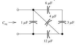
Figure T3.2
Expert Solution & Answer
Want to see the full answer?
Check out a sample textbook solution
Students have asked these similar questions
Pls show neat and whole solution
Pls show neat and whole solution
Need handwritten solution not using chatgpt Or AI
Chapter 3 Solutions
Electrical Engineering: Principles & Applications (7th Edition)
Ch. 3 - What is a dielectric material? Give two examples.Ch. 3 - Briefly discuss how current can flow “through” a...Ch. 3 - What current flows through an ideal capacitor if...Ch. 3 - Describe the internal construction of capacitors.Ch. 3 - A voltage of 50 V appears across a 10F capacitor....Ch. 3 - A 2000F capacitor, initially charged to 100V, is...Ch. 3 - A 5F Capacitor ischarged to 1000 V. Determine the...Ch. 3 - The voltage across a 10F capacitor is given by v...Ch. 3 - The voltage across a 1F capacitor is given by...Ch. 3 - Prior to t = 0, a 100F capacitance is uncharged...
Ch. 3 - The current through a 0.5F capacitor is shown in...Ch. 3 - Determine the capacitor voltage, power, and stored...Ch. 3 - A current given by i(t)=Imcos(t) flows through a...Ch. 3 - The current through a 3F capacitor is shown in...Ch. 3 - A constant (dc) current i(t)=3 mA flows into a 50F...Ch. 3 - The energy stored in a 2F capacitor is 200 J and...Ch. 3 - At t=t0 the voltage across a certain capacitance...Ch. 3 - An unusual capacitor has a capacitance that is a...Ch. 3 - For a resistor, what resistance corresponds to a...Ch. 3 - Suppose we have a very large capacitance (ideally,...Ch. 3 - We want to store sufficient energy in a 001-F...Ch. 3 - A 100F capacitor has a voltage given by v(t)=1010...Ch. 3 - How are capacitances combined in series and in...Ch. 3 - Find the equivalent capacitance for each of the...Ch. 3 - Find the equivalent capacitance between terminals...Ch. 3 - A network has a 5F capacitance in series with the...Ch. 3 - What are the minimum and maximum values of...Ch. 3 - Two initially uncharged capacitors C1=15F and...Ch. 3 - Suppose that we are designing a cardiac pacemaker...Ch. 3 - Suppose that we have two 100F capacitors One is...Ch. 3 - Determine the capacitance of a parallel-plate...Ch. 3 - A 100-pF capacitor is constructed of parallel...Ch. 3 - We have a parallel-plate capacitor with plates of...Ch. 3 - Suppose that we have a 1000-pF parallel-plate...Ch. 3 - Two 1F capacitors have an initial voltage of 100 V...Ch. 3 - Prob. 3.36PCh. 3 - Prob. 3.37PCh. 3 - A parallel-plate capacitor is used as a vibration...Ch. 3 - A 0.1F capacitor has a parasitic series resistance...Ch. 3 - Prob. 3.40PCh. 3 - Briefly discuss how inductors are constructed.Ch. 3 - The current flowing through an inductor is...Ch. 3 - If the current through an ideal inductor is...Ch. 3 - Briefly discuss the fluid-flow analogy for an...Ch. 3 - The current flowing through a 2-H inductance is...Ch. 3 - The current flowing through a 100-mH inductance is...Ch. 3 - The current flowing through a 2-H inductance is...Ch. 3 - The voltage across a 2-H inductance is shown in...Ch. 3 - The voltage across a 10 H inductance is given by...Ch. 3 - A 2-H inductance has i(0) = 0 and v(t)=texp(t) for...Ch. 3 - A constant voltage of 10V is applied to a 50H...Ch. 3 - At t = 0, the current flowing in a 05-H inductance...Ch. 3 - The current through a 100-mH inductance is given...Ch. 3 - Prior to t= 0, the current in a 2-H inductance is...Ch. 3 - At t= 0, a constant 5-V voltage source is applied...Ch. 3 - Prob. 3.56PCh. 3 - Al t= 5 s, the energy stored in a 2-H inductor is...Ch. 3 - What value of inductance (having zero initial...Ch. 3 - To what circuit element does a very large...Ch. 3 - The voltage across an inductance L is given by...Ch. 3 - Discuss how inductances are combined in series and...Ch. 3 - Determine the equivalent inductance for each of...Ch. 3 - Find the equivalent inductance for each of the...Ch. 3 - What is the maximum inductance that can be...Ch. 3 - Suppose we want to combine (in series or in...Ch. 3 - Prob. 3.66PCh. 3 - Two inductances L1=1H and L2=2H are connected in...Ch. 3 - A 10-mH inductor has a parasitic series resistance...Ch. 3 - Draw the equivalent circuit for a real inductor,...Ch. 3 - Suppose that the equivalent circuit shown in...Ch. 3 - Consider the circuit shown in Figure P3.71 in...Ch. 3 - The circuit shown in Figure P3.72 has...Ch. 3 - Describe briefly the physical basis for mutual...Ch. 3 - The mutually coupled inductances in Figure P3.74...Ch. 3 - Repeat Problem P3.74 with the dot placed at the...Ch. 3 - a. Derive an expression for the equivalent...Ch. 3 - Consider the parallel inductors shown in Figure...Ch. 3 - Consider the mutually coupled inductors shown in...Ch. 3 - Mutually coupled inductances have...Ch. 3 - The current through a 200-mH inductance is given...Ch. 3 - A 1-H inductance has iL(0)=0 and vL(t)=texp(t) for...Ch. 3 - The current flowing through a 10F capacitor having...Ch. 3 - Determine the equivalent capacitance Ceq for...Ch. 3 - A certain parallel-plate capacitor has plate...Ch. 3 - A 2-mH inductance has iab=0.3sin(2000t)A . Find an...Ch. 3 - Determine the equivalent inductance Leq between...Ch. 3 - Given that vc(t)=10sin(1000t)V , find vs(t)in the...Ch. 3 - Prob. 3.7PTCh. 3 - The current flowing through a 20F capacitor having...
Knowledge Booster


Learn more about
Need a deep-dive on the concept behind this application? Look no further. Learn more about this topic, electrical-engineering and related others by exploring similar questions and additional content below.Similar questions
- 1) A circuit is given as shown. (a) Find and label the circuit nodes. (6) Determine I, II, I₂ and V, I mm 22 +1 m 50 4 12 12v 2 ти + V ≤1652 50 mv Ми 60arrow_forwardHANDWRITTEN SOLUTION NOT USING CHATGPT PLEASEarrow_forwardDesign a full-wave rectifier power supply using a 9.52:1 transformer. Assume that the outlet is120 V rms @ 60 Hz. Further assume that the diode turn-on voltage V D(on) is 0.7 V. Pick the valueof CL such that vo has a maximum ripple of 1 V p-p . Solve for the average value of vo = Vo (notethat this may be greater than 12 V) and iD(ave) = ID.arrow_forward
- Light-emitting diodes (LEDs) are diodes made with III-V compound semiconductor materials such as aluminum gallium arsenide (AlGaAs), aluminum indium gallium phosphide (AlInGaP) or indium gallium nitride (InGaN), instead of silicon. The LEDs emit light when the device is operated under forward bias. LEDs of different colors have different turn-on voltages VD(on). For example: VD(on) : Red: ~ 1.6 V Yellow: ~ 1.7 V Green: ~ 1.8 V Blue: ~ 2.8 V White: ~ 3.8 V (a) Model these five LEDs with a simplified piecewise linear model (b) A rule of thumb is that it takes about 1 mA of current to “light” an LED while ~ 10 mA is needed for it to appear bright. Use the piecewise linear model for the LEDs, for the over-voltage indicator circuit to the right, find the values of Vin which will cause D1 or D2 to light (i.e. when ID1 or ID2 exceeds 1 mA).arrow_forwardConsider a fixed and updated instrumentation amplifier (where two resistors are lumped into one resistor), analyze the circuit if a common voltage source (VICM) is connected to two inputs. A₁ R₂ + R₁ R₂, RA www www R₁ R₁ www A3 X R₁ R₂ www www R₁₂ + Vo RA A2 V2 O- + R₂ 12 R₁arrow_forwardShow that the input impedance of a lossy transmission line of length L connected to a load impedance of Z is given by Z₁Cosh(yL) + ZoSinh(yL) Zin = Zo ZoCosh(YL) + Z₁Sihh(YL) ex Where Cosh(x) = and Sinh(x) = are the hyperbolic cosine and sine, respectively. 2 2arrow_forward
- A sinusoidal source of V = 10 and Z = 50 - j40 is connected to a 60 lossless transmission line of length 100 m with ẞ = 0.25. What is the Thevenin's equivalent of this system seen looking into the load end of the transmission line?arrow_forward2. On a distortionless transmission line, the voltage wave is given by v(L,t) = 110e0.005L Cos(10³t + 2L) +55e-0.005L Cos(108t-2L) where L is the length of the transmission line as measured from the load. If Z = 30002, find a,ẞ, vp, and Zo.arrow_forwardA 50 transmission line is to be connected to a 72 load through a 1/4 quarter wave matching transformer. (a) What must be the characteristic impedance of the transmission line that is used to form the quarter wave transformer? (b) If the frequency of operation is 7 MHz and the phase velocity through the quarter wave section is 2c/3, what is the length of the quarter wave section? You may assume the transmission line forming the quarter wave section is lossless.arrow_forward
arrow_back_ios
SEE MORE QUESTIONS
arrow_forward_ios
Recommended textbooks for you
 Introductory Circuit Analysis (13th Edition)Electrical EngineeringISBN:9780133923605Author:Robert L. BoylestadPublisher:PEARSON
 Delmar's Standard Textbook Of ElectricityElectrical EngineeringISBN:9781337900348Author:Stephen L. HermanPublisher:Cengage Learning
 Programmable Logic ControllersElectrical EngineeringISBN:9780073373843Author:Frank D. PetruzellaPublisher:McGraw-Hill Education
 Fundamentals of Electric CircuitsElectrical EngineeringISBN:9780078028229Author:Charles K Alexander, Matthew SadikuPublisher:McGraw-Hill Education
 Electric Circuits. (11th Edition)Electrical EngineeringISBN:9780134746968Author:James W. Nilsson, Susan RiedelPublisher:PEARSON
 Engineering ElectromagneticsElectrical EngineeringISBN:9780078028151Author:Hayt, William H. (william Hart), Jr, BUCK, John A.Publisher:Mcgraw-hill Education,
Introductory Circuit Analysis (13th Edition)
Electrical Engineering
ISBN:9780133923605
Author:Robert L. Boylestad
Publisher:PEARSON
Delmar's Standard Textbook Of Electricity
Electrical Engineering
ISBN:9781337900348
Author:Stephen L. Herman
Publisher:Cengage Learning
Programmable Logic Controllers
Electrical Engineering
ISBN:9780073373843
Author:Frank D. Petruzella
Publisher:McGraw-Hill Education
Fundamentals of Electric Circuits
Electrical Engineering
ISBN:9780078028229
Author:Charles K Alexander, Matthew Sadiku
Publisher:McGraw-Hill Education
Electric Circuits. (11th Edition)
Electrical Engineering
ISBN:9780134746968
Author:James W. Nilsson, Susan Riedel
Publisher:PEARSON
Engineering Electromagnetics
Electrical Engineering
ISBN:9780078028151
Author:Hayt, William H. (william Hart), Jr, BUCK, John A.
Publisher:Mcgraw-hill Education,
02 - Sinusoidal AC Voltage Sources in Circuits, Part 1; Author: Math and Science;https://www.youtube.com/watch?v=8zMiIHVMfaw;License: Standard Youtube License