
Electrical Engineering: Principles & Applications (7th Edition)
7th Edition
ISBN: 9780134484143
Author: Allan R. Hambley
Publisher: PEARSON
expand_more
expand_more
format_list_bulleted
Concept explainers
Videos
Textbook Question
Chapter 3, Problem 3.35P
Two
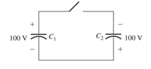
Figure P3.35
Expert Solution & Answer

Trending nowThis is a popular solution!

Students have asked these similar questions
2. Suppose the Laplace transform of a causal signal x(t) is given by
s² +2
X(s) =
S³ + 1
Using the lookup tables for standard Laplace transforms and the Laplace transform
properties, find the Laplace transforms of the following signals. You do not need to
simplify the expressions.
a) x₁(t) = e² x(t) + 38(t − 1) − (t − 2)² u(t − 2)
b) x2(t) = x(2t - 1) + et u(t − 2)
Please explain in detail the steps to solve this. Thank you
6. Answer the following questions. Take help from ChatGPT to answer these questions
(if you need). But write the answers briefly using your own words with no more than
two sentences and make sure you check whether ChatGPT is giving you the
appropriate answers in our context.
a) What is the difference between a regulator and a servo system? Which is harder
to build?
b) What are the advantages and drawbacks of manual control systems over
automatic ones?
c) Does transfer exist for the non-linear systems?
d) Explain the convolution property of the Laplace transform.
e) What are the advantages of using state-space representation?
Chapter 3 Solutions
Electrical Engineering: Principles & Applications (7th Edition)
Ch. 3 - What is a dielectric material? Give two examples.Ch. 3 - Briefly discuss how current can flow “through” a...Ch. 3 - What current flows through an ideal capacitor if...Ch. 3 - Describe the internal construction of capacitors.Ch. 3 - A voltage of 50 V appears across a 10F capacitor....Ch. 3 - A 2000F capacitor, initially charged to 100V, is...Ch. 3 - A 5F Capacitor ischarged to 1000 V. Determine the...Ch. 3 - The voltage across a 10F capacitor is given by v...Ch. 3 - The voltage across a 1F capacitor is given by...Ch. 3 - Prior to t = 0, a 100F capacitance is uncharged...
Ch. 3 - The current through a 0.5F capacitor is shown in...Ch. 3 - Determine the capacitor voltage, power, and stored...Ch. 3 - A current given by i(t)=Imcos(t) flows through a...Ch. 3 - The current through a 3F capacitor is shown in...Ch. 3 - A constant (dc) current i(t)=3 mA flows into a 50F...Ch. 3 - The energy stored in a 2F capacitor is 200 J and...Ch. 3 - At t=t0 the voltage across a certain capacitance...Ch. 3 - An unusual capacitor has a capacitance that is a...Ch. 3 - For a resistor, what resistance corresponds to a...Ch. 3 - Suppose we have a very large capacitance (ideally,...Ch. 3 - We want to store sufficient energy in a 001-F...Ch. 3 - A 100F capacitor has a voltage given by v(t)=1010...Ch. 3 - How are capacitances combined in series and in...Ch. 3 - Find the equivalent capacitance for each of the...Ch. 3 - Find the equivalent capacitance between terminals...Ch. 3 - A network has a 5F capacitance in series with the...Ch. 3 - What are the minimum and maximum values of...Ch. 3 - Two initially uncharged capacitors C1=15F and...Ch. 3 - Suppose that we are designing a cardiac pacemaker...Ch. 3 - Suppose that we have two 100F capacitors One is...Ch. 3 - Determine the capacitance of a parallel-plate...Ch. 3 - A 100-pF capacitor is constructed of parallel...Ch. 3 - We have a parallel-plate capacitor with plates of...Ch. 3 - Suppose that we have a 1000-pF parallel-plate...Ch. 3 - Two 1F capacitors have an initial voltage of 100 V...Ch. 3 - Prob. 3.36PCh. 3 - Prob. 3.37PCh. 3 - A parallel-plate capacitor is used as a vibration...Ch. 3 - A 0.1F capacitor has a parasitic series resistance...Ch. 3 - Prob. 3.40PCh. 3 - Briefly discuss how inductors are constructed.Ch. 3 - The current flowing through an inductor is...Ch. 3 - If the current through an ideal inductor is...Ch. 3 - Briefly discuss the fluid-flow analogy for an...Ch. 3 - The current flowing through a 2-H inductance is...Ch. 3 - The current flowing through a 100-mH inductance is...Ch. 3 - The current flowing through a 2-H inductance is...Ch. 3 - The voltage across a 2-H inductance is shown in...Ch. 3 - The voltage across a 10 H inductance is given by...Ch. 3 - A 2-H inductance has i(0) = 0 and v(t)=texp(t) for...Ch. 3 - A constant voltage of 10V is applied to a 50H...Ch. 3 - At t = 0, the current flowing in a 05-H inductance...Ch. 3 - The current through a 100-mH inductance is given...Ch. 3 - Prior to t= 0, the current in a 2-H inductance is...Ch. 3 - At t= 0, a constant 5-V voltage source is applied...Ch. 3 - Prob. 3.56PCh. 3 - Al t= 5 s, the energy stored in a 2-H inductor is...Ch. 3 - What value of inductance (having zero initial...Ch. 3 - To what circuit element does a very large...Ch. 3 - The voltage across an inductance L is given by...Ch. 3 - Discuss how inductances are combined in series and...Ch. 3 - Determine the equivalent inductance for each of...Ch. 3 - Find the equivalent inductance for each of the...Ch. 3 - What is the maximum inductance that can be...Ch. 3 - Suppose we want to combine (in series or in...Ch. 3 - Prob. 3.66PCh. 3 - Two inductances L1=1H and L2=2H are connected in...Ch. 3 - A 10-mH inductor has a parasitic series resistance...Ch. 3 - Draw the equivalent circuit for a real inductor,...Ch. 3 - Suppose that the equivalent circuit shown in...Ch. 3 - Consider the circuit shown in Figure P3.71 in...Ch. 3 - The circuit shown in Figure P3.72 has...Ch. 3 - Describe briefly the physical basis for mutual...Ch. 3 - The mutually coupled inductances in Figure P3.74...Ch. 3 - Repeat Problem P3.74 with the dot placed at the...Ch. 3 - a. Derive an expression for the equivalent...Ch. 3 - Consider the parallel inductors shown in Figure...Ch. 3 - Consider the mutually coupled inductors shown in...Ch. 3 - Mutually coupled inductances have...Ch. 3 - The current through a 200-mH inductance is given...Ch. 3 - A 1-H inductance has iL(0)=0 and vL(t)=texp(t) for...Ch. 3 - The current flowing through a 10F capacitor having...Ch. 3 - Determine the equivalent capacitance Ceq for...Ch. 3 - A certain parallel-plate capacitor has plate...Ch. 3 - A 2-mH inductance has iab=0.3sin(2000t)A . Find an...Ch. 3 - Determine the equivalent inductance Leq between...Ch. 3 - Given that vc(t)=10sin(1000t)V , find vs(t)in the...Ch. 3 - Prob. 3.7PTCh. 3 - The current flowing through a 20F capacitor having...
Knowledge Booster


Learn more about
Need a deep-dive on the concept behind this application? Look no further. Learn more about this topic, electrical-engineering and related others by exploring similar questions and additional content below.Similar questions
- 4. Find the differential equation of the following system whose transfer function is given by S+3 H(s) = s3 +3s+2arrow_forwardPreliminary Laboratory (Prelab) Work Complete the following tasks in the space provided below for the circuit shown in Figure 2. 1. Use voltage division to compute the phasor voltages VR and Vc assuming nominal values of R = 1000[2], C = 0.01[u], and a cosinusoidal time-domain source voltage signal given by equation 5 below. Voltage division must be used to receive any credit. (10 points) equation (5) Vs(t) = VRMSCOS(ct + 0) = 5cos(@t + 0) = 5cos(62832t + 0) = 5cos(62832t) [V] =VRMSCOS(2лft + 0) = 5cos[2л(10000)t + 0] = 5cos[2л(10000)t] [V] 2. Compute the phasor current, Is. (3 points) 3. Calculate the complex power, S, active power, P, and reactive power, Q, for the circuit. (4 points) 4. Construct the phasor diagram for the circuit, and show mathematically that the phasor (vector) sum of the phasor voltages VR and Vc is equal to Vs. (3 points) Agilent 33210A (BECC4242) or Vs Keysight 33500B (BECC4261) Function Generators Is R w + VR Vc + + Zc V out =Vc Figure 2: RC circuit connected…arrow_forwardPlease explain in detail. My answer for the first question is 15/2. I am more confused about how to do the graphing part and figure how long it will take to reach its final value. Thank you, I will like this.arrow_forward
- This is the 3rd time i'm asking this. SOLVE THIS AND FIND V0 , the last answer i was given is -2V which is not even one of the listed options. the listed options are: 12V,4V,24V,6V. first answer given to me was 4V but after i simulated on ltspice albeit i'm not sure if i simulated correct i got a different answer and when i solved it myself i got a different answer. this is my last remaining question. PLEASE SOLVE CORRECTLY AND PROPERLY. NODAL ANALYSIS IS BEST TO USE HERE. IT IS AN IDEAL OP-AMP. SIMULATE USING LTSPICE AND GIVE ME FINAL ANSWER IF POSSIBLE AS THAT IS ALL I CARE ABOUT NOT THE PROCESS. THANK YOU. WILL UPVOTE CORRECT ANSWER, but downvote wrong answer.arrow_forwardFind the exact value of V0. This question was already asked here and the answer was 4V i solved it myself and got a different answer and when i simulated it i also got a different answer.But i might be wrong. so please solve this for me and IF POSSIBLE simulate it so we can be 100% sure that the answer is correct as it's very important that i understand where i went wrong.arrow_forwardFind load flow Solution 1.2 20 Z12 = 0.01+jo.03 in Z₁4=0.02+0.04 и а 9.01+10.03 0.02+0.04 0.01+0.03 58-1 Vek 1.05 100 MVA Pe=230 MW 150 MW w 140 MW 01012 +0.035 80 M√ar 723=0.01+0.03 90 mvare Z34 = 0.012+ 10.035arrow_forward
- SD = 100 MVA 1.12° 150mw ← 0.01+0.03 10.02 -0.04 Too M P = 250 MW 0.02+0.04 0.012 jo.03 $ (V3)=1.05 P.4 -03 = = 200 MW 212=0.01+10.03 Zzze 0.02 +10.04 214=0.02+10.04 Z34 = 0.012+10.03arrow_forwardChoose the correct answer to the following questions: 1- What is the total power radiated in Watts for the power density W = a) 4π² b) 8m²/3 2- Fresnel zone is also called as sine W/m²? 3r² c) 4π²/3 d) 2π²/3 a) Near Field b) Far Field c) Electrostatic Field d) Reactive Field 3- The far-field distance at 900 MHz, if the maximum antenna dimension is 0.75 m is.... a) 3.375 m b) 3.5m c) 3.375 cm d) none 4- The antenna gain is on input power to antenna and on power due to ohmic losses. c) Independent, dependent d) a) Independent, independent b) Dependent, independent Dependent, dependent 5- If beam width of the antenna increases, then directivity. a) Decreases b) Increases c) Remains unchanged d) Depends on type of antennaarrow_forwardplease solve this and clarify each step. thanksarrow_forward
- The input reactance of 1/2 dipole with radius of 1/30 is given as shown in figure below, Assuming the wire of dipole is conductor 5.6*107 S/m, determine at f=1 GHz the a- Loss resistance, b- Radiation efficiency c- Reflection efficiency when the antenna is connected to T.L shown in the figure. Rr Ro= 50 2 Avg/4 RL -j100 [In(l/a) 1.5] tan(ẞ1)arrow_forwardFind Zeq here. i already had one solution written to me but it's wrong. my main question is. i know that i do the parallel connection first so 2x2 / 2+2 = 1ohm but what i'm asking is since it's an open terminal is R3,2(parallel resistors) in series to R1? or should i first do R3,2 // to ZL and then add R1 in series? PLEASE READ THIS. and solve properly. EXPLAIN WHAT I ASKED PROPERLY. UPVOTE WILL BE GIVEN.arrow_forwardThe E-field pattern of an antenna, independent of o, varies as follows: E = 0 7100 0° ≤0≤45° 45° < 0 ≤ 90° 90° < 0 ≤ 180° (a) What is the directivity of this antenna? (b) What is the radiation resistance of the antenna at 200 m from it if the field is equal to 10 V/m (rms) for 0 = 0° at that distance and the terminal current is 5 A (rms)?arrow_forward
arrow_back_ios
SEE MORE QUESTIONS
arrow_forward_ios
Recommended textbooks for you
 Delmar's Standard Textbook Of ElectricityElectrical EngineeringISBN:9781337900348Author:Stephen L. HermanPublisher:Cengage Learning
Delmar's Standard Textbook Of Electricity
Electrical Engineering
ISBN:9781337900348
Author:Stephen L. Herman
Publisher:Cengage Learning
Electrical Measuring Instruments - Testing Equipment Electrical - Types of Electrical Meters; Author: Learning Engineering;https://www.youtube.com/watch?v=gkeJzRrwe5k;License: Standard YouTube License, CC-BY
01 - Instantaneous Power in AC Circuit Analysis (Electrical Engineering); Author: Math and Science;https://www.youtube.com/watch?v=If25y4Nhvw4;License: Standard YouTube License, CC-BY