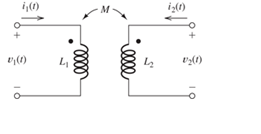
The mutually coupled inductances in Figure P3.74 have L 1 = 1 H , L 2 = 2 H , and M = 1 H. Furthermore, i 1 ( t ) = sin ( 10 t ) and i 2 ( t ) = 0.5 sin ( 10 t ) . Find expressions for v 1 ( t ) and v 2 ( t ) . The arguments of the sine functions are in radians. Figure P374
The mutually coupled inductances in Figure P3.74 have L 1 = 1 H , L 2 = 2 H , and M = 1 H. Furthermore, i 1 ( t ) = sin ( 10 t ) and i 2 ( t ) = 0.5 sin ( 10 t ) . Find expressions for v 1 ( t ) and v 2 ( t ) . The arguments of the sine functions are in radians. Figure P374
The mutually coupled inductances in Figure P3.74 have
L
1
=
1
H
,
L
2
=
2
H
, and M = 1 H. Furthermore,
i
1
(
t
)
=
sin
(
10
t
)
and
i
2
(
t
)
=
0.5
sin
(
10
t
)
. Find expressions for
v
1
(
t
)
and
v
2
(
t
)
. The arguments of the sine functions are in radians.
A 1200-ampere service was installed, consisting of three sets of 600 kcmil THHN/THWN copper conductors per phase. The electrical contractor was careful to cut theconductors the same length. When the utility crew made up the connections at theservice heads, they cut the conductors to different lengths to make their connectionssimpler. The actual lengths of the service-entrance conductors in a given phase ended up being20 ft (6.1 m), 22 ft (6.7 m), and 24 ft (7.3 m). The maximum ampacity of a 600-kcmilTHHN/THWN copper conductor is 420 amperes using the 75°C column of Table310.16. This is more than adequate for the calculated 1200 amperes when three conductors are run in parallel. Determine how the load of 1200 amperes would divide in each of the three paralleledconductors in a phase.
Determine the conductor sizes for a feeder to a panelboard. It is a 120/240-volt,single-phase system. The OCPD has a rating of 100 amperes. The calculated load is15,600 VA. All the loads are 120 volts.
Calculate the neutral current in a 120/240-volt, single-phase system when the current inphase A is 20 amperes and the current in phase B is 40 amperes. The load is resistive.
Calculate the neutral current in a 208Y/120-volt, 3-phase, 4-wire system when thecurrent in phase A is 0, in phase B is 40, and in phase C is 60 amperes. The load isresistive
Need a deep-dive on the concept behind this application? Look no further. Learn more about this topic, electrical-engineering and related others by exploring similar questions and additional content below.
Inductance of Three Phase Transmission lines (Symmetrical and Unsymmetrical Configurations); Author: Ravindra Prasad Pendyala;https://www.youtube.com/watch?v=CbFBxjfHYFY;License: Standard Youtube License


 Introductory Circuit Analysis (13th Edition)Electrical EngineeringISBN:9780133923605Author:Robert L. BoylestadPublisher:PEARSON
 Delmar's Standard Textbook Of ElectricityElectrical EngineeringISBN:9781337900348Author:Stephen L. HermanPublisher:Cengage Learning
 Programmable Logic ControllersElectrical EngineeringISBN:9780073373843Author:Frank D. PetruzellaPublisher:McGraw-Hill Education
 Fundamentals of Electric CircuitsElectrical EngineeringISBN:9780078028229Author:Charles K Alexander, Matthew SadikuPublisher:McGraw-Hill Education
 Electric Circuits. (11th Edition)Electrical EngineeringISBN:9780134746968Author:James W. Nilsson, Susan RiedelPublisher:PEARSON
 Engineering ElectromagneticsElectrical EngineeringISBN:9780078028151Author:Hayt, William H. (william Hart), Jr, BUCK, John A.Publisher:Mcgraw-hill Education,