
Mechanics of Materials (MindTap Course List)
9th Edition
ISBN: 9781337093347
Author: Barry J. Goodno, James M. Gere
Publisher: Cengage Learning
expand_more
expand_more
format_list_bulleted
Concept explainers
Videos
Textbook Question
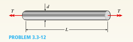
Chapter 3, Problem 3.3.12P
A propeller shaft for a small yacht is made of a solid steel bar 104 mm in diameter. The allowable stress in shear is 48 MPa, and the allowable rate of twist is 2.0° in 3.5 meters.
(a) Assuming that the shear modulus of elasticity is G = 80 GPa, determine the maximum torque that can be applied to the shaft.
(b) Repeat part (a) if the shaft is now hollow with an inner diameter of 5d18. Compare values to corresponding values from part (a).
Expert Solution & Answer

Trending nowThis is a popular solution!

Students have asked these similar questions
1. Describe each of the tolerances in the following drawing:
0.01 A
09±0.025
.10±0.01
0.015 AB
6.76
08.51
03±0.05
0.015 MAB
14±0.03
60
14±0.02
12±0.08
0.01 A B
what is the intake flow in cfm of a 5.3 liter engine running at 6200 RPM with a volumetric efficiency of 86%. If we supercharge it to flow 610 CFM what is the volumetric efficiency?
Quiz/An eccentrically loaded bracket is welded to the support as shown in Figure below. The load is static. The weld size
for weld w1 is h1=6mm, for w2 h2 5mm, and for w3 is h3 -5.5 mm. Determine the safety factor (S.f) for the welds.
F=22 kN. Use an AWS Electrode type (E90xx).
140
101.15
REDMI NOTE 8 PRO
AI QUAD CAMERA
F
Chapter 3 Solutions
Mechanics of Materials (MindTap Course List)
Ch. 3 - A circular tube is subjected to torque Tat its...Ch. 3 - -2. A plastic bar of diameter d = 56 mm is to be...Ch. 3 - A copper rod of length L = 18.0 in. is to be...Ch. 3 - A circular steel tube of length L = 1.0 m is...Ch. 3 - Solve the preceding problem if the length L = 56...Ch. 3 - A circular aluminum tube subjected to pure torsion...Ch. 3 - A solid steel bar of circular cross section has...Ch. 3 - A solid copper bar of circular cross section has...Ch. 3 - Repeat Problem 3.3-1, but now use a circular tube...Ch. 3 - A copper tube with circular cross section has...
Ch. 3 - A prospector uses a hand-powered winch (see...Ch. 3 - When drilling a hole in a table leg, a furniture...Ch. 3 - While removing a wheel to change a tire, a driver...Ch. 3 - -8 An aluminum bar of solid circular cross section...Ch. 3 - A high-strength steel drill rod used for boring a...Ch. 3 - The steel shaft of a socket wrench has a diameter...Ch. 3 - A circular tube of aluminum is subjected to...Ch. 3 - A propeller shaft for a small yacht is made of a...Ch. 3 - Three identical circular disks A, B, and Care...Ch. 3 - The steel axle of a large winch on an ocean liner...Ch. 3 - A hollow steel shaft used in a construction auger...Ch. 3 - Solve the preceding problem if the shaft has an...Ch. 3 - A vertical pole of solid, circular cross section...Ch. 3 - A vertical pole of solid, circular cross section...Ch. 3 - A solid brass bar of diameter d = 1.25 in. is...Ch. 3 - A hollow aluminum tube used in a roof structure...Ch. 3 - A circular tube of inner radius r1and outer radius...Ch. 3 - .1 A stepped shaft ABC consisting of two solid...Ch. 3 - A circular tube of outer diameter d3= 70 mm and...Ch. 3 - A stepped shaft ABCD consisting of solid circular...Ch. 3 - A solid, circular bar ABC consists of two...Ch. 3 - A hollow tube ABCDE constructed of monel metal is...Ch. 3 - A shaft with a solid, circular cross section...Ch. 3 - Prob. 3.4.7PCh. 3 - Two sections of steel drill pipe, joined by bolted...Ch. 3 - Prob. 3.4.9PCh. 3 - -10. A tapered bar AB with a solid circular cross...Ch. 3 - A tapered bar AB with a solid circular cross...Ch. 3 - The bar shown in the figure is tapered linearly...Ch. 3 - The non prismatic, cantilever circular bar shown...Ch. 3 - A uniformly tapered tube AB with a hollow circular...Ch. 3 - A uniformly tapered aluminum-alloy tube AB with a...Ch. 3 - For the thin nonprismatic steel pipe of constant...Ch. 3 - .17 A mountain-bike rider going uphill applies...Ch. 3 - A prismatic bar AB of length L and solid circular...Ch. 3 - A prismatic bar AB with a solid circular cross...Ch. 3 - A magnesium-alloy wire of diameter d = 4mm and...Ch. 3 - A nonprismatic bar ABC with a solid circular cross...Ch. 3 - -22 Two tubes (AB, BC) of the same material arc...Ch. 3 - A circular copper bar with diameter d = 3 in. is...Ch. 3 - A circular steel tube with an outer diameter of 75...Ch. 3 - A hollow aluminum shaft (see figure) has an...Ch. 3 - A hollow steel bar (G = 80 GPa ) is twisted by...Ch. 3 - A tubular bar with outside diameterd2= 4.0 in, is...Ch. 3 - A solid circular bar of diameter d = 50 mm (see...Ch. 3 - -7 A steel tube (G = 11.5 x 10⁶ psi) has an outer...Ch. 3 - A solid circular bar of steel (G = 78 GPa)...Ch. 3 - The normal strain in the 45n direction on the...Ch. 3 - An aluminum tube has inside diameter dx= 50 mm,...Ch. 3 - -11 A solid steel bar (G = 11.8 X 10⁶ psi ) of...Ch. 3 - A solid aluminum bar (G = 27 GPa ) of diameter d =...Ch. 3 - Two circular aluminum pipes of equal length L = 24...Ch. 3 - A generator shaft in a small hydroelectric plant...Ch. 3 - A motor drives a shaft at 12 Hz and delivers 20 kW...Ch. 3 - A motor driving a solid circular steel shaft with...Ch. 3 - Prob. 3.7.4PCh. 3 - The propeller shaft of a large ship has an outside...Ch. 3 - The drive shaft for a truck (outer diameter 60 mm...Ch. 3 - A hollow circular shaft for use in a pumping...Ch. 3 - A tubular shaft being designed for use on a...Ch. 3 - A propeller shaft of solid circular cross section...Ch. 3 - What is the maximum power that can be delivered by...Ch. 3 - A motor delivers 275 hp at 1000 rpm to the end of...Ch. 3 - Prob. 3.7.12PCh. 3 - A solid circular bar ABCD with fixed supports is...Ch. 3 - A solid circular bar A BCD with fixed supports at...Ch. 3 - A solid circular shaft AB of diameter d is fixed...Ch. 3 - A ho 1 low st e el shaft ACB of outside diameter...Ch. 3 - A stepped shaft ACB having solid circular cross...Ch. 3 - A stepped shaft ACB having solid circular cross...Ch. 3 - A stepped shaft ACE is held against rotation at...Ch. 3 - A solid circulai' aluminum bar AB is fixed at both...Ch. 3 - Two sections of steel drill pipe, joined by bolted...Ch. 3 - A circular bar AB of length L is fixed against...Ch. 3 - A circular bar AB with ends fixed against rotation...Ch. 3 - A solid steel bar of diameter d1= 25.0 mm is...Ch. 3 - A solid steel bar of diameter d1= 1.50 in. is...Ch. 3 - The composite shaft shown in the figure is...Ch. 3 - The composite shaft shown in the figure is...Ch. 3 - A steel shaft (Gs= 80 GPa) of total length L = 3.0...Ch. 3 - A uniformly tapered aluminum-ally tube AB of...Ch. 3 - Two pipes {L, = 2.5 m and L, = 1.5 m) are joined...Ch. 3 - A solid circular bar of steel (G = 1L4 × 106 psi)...Ch. 3 - A solid circular bar of copper (G = 45 GPa) with...Ch. 3 - A stepped shaft of solid circular cross sections...Ch. 3 - A stepped shaft of solid circular cross sections...Ch. 3 - A circular tube AB is fixed at one end and free at...Ch. 3 - A cantilever bar of circular cross section and...Ch. 3 - Obtain a formula for the strain energy U of the...Ch. 3 - A statically indeterminate stepped shaft ACE is...Ch. 3 - Derive a formula for the strain energy U of the...Ch. 3 - A thin-walled hollow tube AB of conical shape has...Ch. 3 - A hollow circular tube A fits over the end of a...Ch. 3 - A heavy flywheel rotating at n revolutions per...Ch. 3 - A hollow circular tube having an inside diameter...Ch. 3 - A solid circular bar having diameter d is to be...Ch. 3 - A thin-walled aluminum tube of rectangular cross...Ch. 3 - A thin-walled steel tube of rectangular cross...Ch. 3 - A square tube section has side dimension of 20 in....Ch. 3 - A thin-walled circular tube and a solid circular...Ch. 3 - A thin-walled steel tube having an elliptical...Ch. 3 - Calculate the shear stress and the angle of twist...Ch. 3 - A torque T is applied to a thin-walled tube having...Ch. 3 - Compare the angle of twist 1 for a thin-walled...Ch. 3 - A tubular aluminum bar (G = 4 × 10⁶ psi) of square...Ch. 3 - A thin tubular shaft with a circular cross section...Ch. 3 - A thin-walled rectangular tube has uniform...Ch. 3 - A long, thin-walled tapered tube AB with a...Ch. 3 - A stepped shaft consisting of solid circular...Ch. 3 - A stepped shaft with diameters D1= 40 mm and D2=...Ch. 3 - A full quarter-circular fillet is used at the...Ch. 3 - The stepped shaft shown in the figure is required...Ch. 3 - A stepped shaft (see figure) has diameter D2= 1.5...
Knowledge Booster


Learn more about
Need a deep-dive on the concept behind this application? Look no further. Learn more about this topic, mechanical-engineering and related others by exploring similar questions and additional content below.Similar questions
- Quiz/An eccentrically loaded bracket is welded to the support as shown in Figure below. The load is static. The weld size for weld w1 is h1 = 4mm, for w2 h2 = 6mm, and for w3 is h3 -6.5 mm. Determine the safety factor (S.f) for the welds. F=29 kN. Use an AWS Electrode type (E100xx). BES FOR P 163 mm 133 mm 140 mmarrow_forwardExample -4s F(s) = = (s²+4)² As + B Cs+D + (s²+4) (s²+4)² (s²+4) (H.W)arrow_forwardQ1/ Find L[t et sin t] Q2/ Find The Laplace Transform f(t) = [sint [sint 0arrow_forwardb) The 50 mm diameter rod is placed in a hole, lubricated walls. There is no clearance between the rod and the sides of the hole. Determine the change in length of the rod if an 8 kN load is applied. Take E(brass) = 80 GPa; v = 0.55 [10] 50 mmm 300 rat 3arrow_forwardThe Mach number NM for flow of a perfect gas in a pipe depends upon the specific-heat ratio k (dimensionless), the pressure p, the density ρ, and the velocity V. Obtain by dimensional reasoning the form of the Mach number expression. (Buckingham pi)Answer: NM = f(V/sqrt(p/ρ), k)arrow_forwardoyfr 3. The figure shows a frame under the influence of an external loading made up of five forces and two moments. Use the scalar method to calculate moments. a. Write the resultant force of the external loading in Cartesian vector form. b. Determine the & direction of the resultant moment of the external loading about A. 15 cm 18 cm 2.2 N-m B 50 N 45° 10 cm 48 N.m 250 N 60 N 20 21 50 N 25 cm 100 N A 118, 27cm 5, 4:1arrow_forwardAssume the Link AO is the input and revolves 360°, determine a. the coordinates of limit positions of point B, b. the angles (AOC) corresponding to the limit positionsarrow_forwardoyfr 3. The figure shows a frame under the influence of an external loading made up of five forces and two moments. Use the scalar method to calculate moments. a. Write the resultant force of the external loading in Cartesian vector form. b. Determine the & direction of the resultant moment of the external loading about A. 15 cm 18 cm 2.2 N-m B 50 N 45° 10 cm 48 N.m 250 N 60 N 20 21 50 N 25 cm 100 N A 118, 27cm 5, 4:1arrow_forwardThe 2-mass system shown below depicts a disk which rotates about its center and has rotational moment of inertia Jo and radius r. The angular displacement of the disk is given by 0. The spring with constant k₂ is attached to the disk at a distance from the center. The mass m has linear displacement & and is subject to an external force u. When the system is at equilibrium, the spring forces due to k₁ and k₂ are zero. Neglect gravity and aerodynamic drag in this problem. You may assume the small angle approximation which implies (i) that the springs and dampers remain in their horizontal / vertical configurations and (ii) that the linear displacement d of a point on the edge of the disk can be approximated by d≈re. Ө K2 www m 4 Cz 777777 Jo Make the following assumptions when analyzing the forces and torques: тв 2 0>0, 0>0, x> > 0, >0 Derive the differential equations of motion for this dynamic system. Start by sketching LARGE and carefully drawn free-body-diagrams for the disk and the…arrow_forwardA linear system is one that satisfies the principle of superposition. In other words, if an input u₁ yields the output y₁, and an input u2 yields the output y2, the system is said to be linear if a com- bination of the inputs u = u₁ + u2 yield the sum of the outputs y = y1 + y2. Using this fact, determine the output y(t) of the following linear system: given the input: P(s) = = Y(s) U(s) = s+1 s+10 u(t) = e−2+ sin(t) =earrow_forwardThe manometer fluid in the figure given below is mercury where D = 3 in and h = 1 in. Estimate the volume flow in the tube (ft3/s) if the flowing fluid is gasoline at 20°C and 1 atm. The density of mercury and gasoline are 26.34 slug/ft3 and 1.32 slug/ft3 respectively. The gravitational force is 32.2 ft/s2.arrow_forwardUsing the Bernoulli equation to find the general solution. If an initial condition is given, find the particular solution. y' + xy = xy¯¹, y(0) = 3arrow_forwardarrow_back_iosSEE MORE QUESTIONSarrow_forward_ios
Recommended textbooks for you
 Mechanics of Materials (MindTap Course List)Mechanical EngineeringISBN:9781337093347Author:Barry J. Goodno, James M. GerePublisher:Cengage Learning
Mechanics of Materials (MindTap Course List)
Mechanical Engineering
ISBN:9781337093347
Author:Barry J. Goodno, James M. Gere
Publisher:Cengage Learning
Everything About COMBINED LOADING in 10 Minutes! Mechanics of Materials; Author: Less Boring Lectures;https://www.youtube.com/watch?v=N-PlI900hSg;License: Standard youtube license