
Mechanics of Materials (MindTap Course List)
9th Edition
ISBN: 9781337093347
Author: Barry J. Goodno, James M. Gere
Publisher: Cengage Learning
expand_more
expand_more
format_list_bulleted
Concept explainers
Videos
Textbook Question
Chapter 3, Problem 3.8.17P
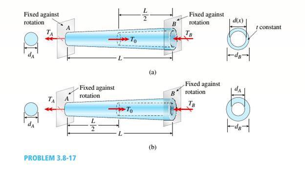
A uniformly tapered aluminum-ally tube AB of circular cross section and length L is fixed against rotation at A and B, as shown in the figure. The outside diameters at the ends are dAand dA.A hollow section of lenth L/2 and constant thickness t = dA/10 is cast into the tube and extends from B half-way toward A. Torque T0is applied at L/2.
(a) Find the reactive torques at the supports, TA and TB. Use numerical values as follows: dA = 2.5 in., L = 48., G = 309 × 106 psi, and T0= 40,000 in.-lb.
(b) Repeat part (a) if the hollow sections has constant diameter dA.
Expert Solution & Answer
Want to see the full answer?
Check out a sample textbook solution
Students have asked these similar questions
One thousand kg/h of a (50-50 wt%) acetone-in-water solution is to be extracted at 25C in a continuous,
countercurrent system with pure 1,1,2-trichloroethane to obtain a raffinate containing 10 wt% acetone. Using the
following equilibrium data, determine with an equilateral-triangle diagram:
a- the minimum flow rate of solvent;
b- the number of stages required for a solvent rate equal to 1.5 times minimum, and composition of each
streamleaving each stage.
c- Repeat the calculation of (a) and (b) if the solvent used has purity 93wt% (4wr% acetone, 3wt% water
impurities)
acetone water
1,1,2-trichloroethane
Raffinate. Weight
Extract. Weight
0.6
0.13
0.27
Fraction Acetone
Fraction Acetone
0.5
0.04
0.46
0.44
0.56
0.4
0.03
0.57
0.29
0.40
0.3
0.02
0.68
0.12
0.18
0.2
0.015
0.785
0.0
0.0
0.1
0.01
0.89
0.55
0.35
0.1
0.5
0.43
0.07
0.4
0.57
0.03
0.3
0.68
0.02
0.2
0.79
0.01
0.1
0.895
0.005
2500 kg/hr of (20-80) nicotine water solution is to be extracted with benzene containing 0.5% nicotine in
the 1st and 2ed stages while the 3rd stage is free of nicotine. Cross- current operation is used with different amounts
of solvent for each stages 2000kg/hr in the 1st stage, 2300 kg/hr in the 2nd stage, 2600 kg/hr in the 3rd,
determine: -
a- The final raffinate concentration and % extraction.
b-
b- The minimum amount of solvent required for counter-current operation if the minimum concentration
will be reduced to 5% in the outlet raffinate.
Equilibrium data
Wt % Nicotine in water
Wt % Nicotine in benzene
0
4
16
25
0
4
21
30
Quiz/An eccentrically loaded bracket is welded to the support as shown in Figure below. The load is static. The weld size
for weld w1 is h1=6mm, for w2 h2 5mm, and for w3 is h3 -5.5 mm. Determine the safety factor (S.f) for the welds.
F=22 kN. Use an AWS Electrode type (E90xx).
140
101.15
REDMI NOTE 8 PRO
AI QUAD CAMERA
F
Chapter 3 Solutions
Mechanics of Materials (MindTap Course List)
Ch. 3 - A circular tube is subjected to torque Tat its...Ch. 3 - -2. A plastic bar of diameter d = 56 mm is to be...Ch. 3 - A copper rod of length L = 18.0 in. is to be...Ch. 3 - A circular steel tube of length L = 1.0 m is...Ch. 3 - Solve the preceding problem if the length L = 56...Ch. 3 - A circular aluminum tube subjected to pure torsion...Ch. 3 - A solid steel bar of circular cross section has...Ch. 3 - A solid copper bar of circular cross section has...Ch. 3 - Repeat Problem 3.3-1, but now use a circular tube...Ch. 3 - A copper tube with circular cross section has...
Ch. 3 - A prospector uses a hand-powered winch (see...Ch. 3 - When drilling a hole in a table leg, a furniture...Ch. 3 - While removing a wheel to change a tire, a driver...Ch. 3 - -8 An aluminum bar of solid circular cross section...Ch. 3 - A high-strength steel drill rod used for boring a...Ch. 3 - The steel shaft of a socket wrench has a diameter...Ch. 3 - A circular tube of aluminum is subjected to...Ch. 3 - A propeller shaft for a small yacht is made of a...Ch. 3 - Three identical circular disks A, B, and Care...Ch. 3 - The steel axle of a large winch on an ocean liner...Ch. 3 - A hollow steel shaft used in a construction auger...Ch. 3 - Solve the preceding problem if the shaft has an...Ch. 3 - A vertical pole of solid, circular cross section...Ch. 3 - A vertical pole of solid, circular cross section...Ch. 3 - A solid brass bar of diameter d = 1.25 in. is...Ch. 3 - A hollow aluminum tube used in a roof structure...Ch. 3 - A circular tube of inner radius r1and outer radius...Ch. 3 - .1 A stepped shaft ABC consisting of two solid...Ch. 3 - A circular tube of outer diameter d3= 70 mm and...Ch. 3 - A stepped shaft ABCD consisting of solid circular...Ch. 3 - A solid, circular bar ABC consists of two...Ch. 3 - A hollow tube ABCDE constructed of monel metal is...Ch. 3 - A shaft with a solid, circular cross section...Ch. 3 - Prob. 3.4.7PCh. 3 - Two sections of steel drill pipe, joined by bolted...Ch. 3 - Prob. 3.4.9PCh. 3 - -10. A tapered bar AB with a solid circular cross...Ch. 3 - A tapered bar AB with a solid circular cross...Ch. 3 - The bar shown in the figure is tapered linearly...Ch. 3 - The non prismatic, cantilever circular bar shown...Ch. 3 - A uniformly tapered tube AB with a hollow circular...Ch. 3 - A uniformly tapered aluminum-alloy tube AB with a...Ch. 3 - For the thin nonprismatic steel pipe of constant...Ch. 3 - .17 A mountain-bike rider going uphill applies...Ch. 3 - A prismatic bar AB of length L and solid circular...Ch. 3 - A prismatic bar AB with a solid circular cross...Ch. 3 - A magnesium-alloy wire of diameter d = 4mm and...Ch. 3 - A nonprismatic bar ABC with a solid circular cross...Ch. 3 - -22 Two tubes (AB, BC) of the same material arc...Ch. 3 - A circular copper bar with diameter d = 3 in. is...Ch. 3 - A circular steel tube with an outer diameter of 75...Ch. 3 - A hollow aluminum shaft (see figure) has an...Ch. 3 - A hollow steel bar (G = 80 GPa ) is twisted by...Ch. 3 - A tubular bar with outside diameterd2= 4.0 in, is...Ch. 3 - A solid circular bar of diameter d = 50 mm (see...Ch. 3 - -7 A steel tube (G = 11.5 x 10⁶ psi) has an outer...Ch. 3 - A solid circular bar of steel (G = 78 GPa)...Ch. 3 - The normal strain in the 45n direction on the...Ch. 3 - An aluminum tube has inside diameter dx= 50 mm,...Ch. 3 - -11 A solid steel bar (G = 11.8 X 10⁶ psi ) of...Ch. 3 - A solid aluminum bar (G = 27 GPa ) of diameter d =...Ch. 3 - Two circular aluminum pipes of equal length L = 24...Ch. 3 - A generator shaft in a small hydroelectric plant...Ch. 3 - A motor drives a shaft at 12 Hz and delivers 20 kW...Ch. 3 - A motor driving a solid circular steel shaft with...Ch. 3 - Prob. 3.7.4PCh. 3 - The propeller shaft of a large ship has an outside...Ch. 3 - The drive shaft for a truck (outer diameter 60 mm...Ch. 3 - A hollow circular shaft for use in a pumping...Ch. 3 - A tubular shaft being designed for use on a...Ch. 3 - A propeller shaft of solid circular cross section...Ch. 3 - What is the maximum power that can be delivered by...Ch. 3 - A motor delivers 275 hp at 1000 rpm to the end of...Ch. 3 - Prob. 3.7.12PCh. 3 - A solid circular bar ABCD with fixed supports is...Ch. 3 - A solid circular bar A BCD with fixed supports at...Ch. 3 - A solid circular shaft AB of diameter d is fixed...Ch. 3 - A ho 1 low st e el shaft ACB of outside diameter...Ch. 3 - A stepped shaft ACB having solid circular cross...Ch. 3 - A stepped shaft ACB having solid circular cross...Ch. 3 - A stepped shaft ACE is held against rotation at...Ch. 3 - A solid circulai' aluminum bar AB is fixed at both...Ch. 3 - Two sections of steel drill pipe, joined by bolted...Ch. 3 - A circular bar AB of length L is fixed against...Ch. 3 - A circular bar AB with ends fixed against rotation...Ch. 3 - A solid steel bar of diameter d1= 25.0 mm is...Ch. 3 - A solid steel bar of diameter d1= 1.50 in. is...Ch. 3 - The composite shaft shown in the figure is...Ch. 3 - The composite shaft shown in the figure is...Ch. 3 - A steel shaft (Gs= 80 GPa) of total length L = 3.0...Ch. 3 - A uniformly tapered aluminum-ally tube AB of...Ch. 3 - Two pipes {L, = 2.5 m and L, = 1.5 m) are joined...Ch. 3 - A solid circular bar of steel (G = 1L4 × 106 psi)...Ch. 3 - A solid circular bar of copper (G = 45 GPa) with...Ch. 3 - A stepped shaft of solid circular cross sections...Ch. 3 - A stepped shaft of solid circular cross sections...Ch. 3 - A circular tube AB is fixed at one end and free at...Ch. 3 - A cantilever bar of circular cross section and...Ch. 3 - Obtain a formula for the strain energy U of the...Ch. 3 - A statically indeterminate stepped shaft ACE is...Ch. 3 - Derive a formula for the strain energy U of the...Ch. 3 - A thin-walled hollow tube AB of conical shape has...Ch. 3 - A hollow circular tube A fits over the end of a...Ch. 3 - A heavy flywheel rotating at n revolutions per...Ch. 3 - A hollow circular tube having an inside diameter...Ch. 3 - A solid circular bar having diameter d is to be...Ch. 3 - A thin-walled aluminum tube of rectangular cross...Ch. 3 - A thin-walled steel tube of rectangular cross...Ch. 3 - A square tube section has side dimension of 20 in....Ch. 3 - A thin-walled circular tube and a solid circular...Ch. 3 - A thin-walled steel tube having an elliptical...Ch. 3 - Calculate the shear stress and the angle of twist...Ch. 3 - A torque T is applied to a thin-walled tube having...Ch. 3 - Compare the angle of twist 1 for a thin-walled...Ch. 3 - A tubular aluminum bar (G = 4 × 10⁶ psi) of square...Ch. 3 - A thin tubular shaft with a circular cross section...Ch. 3 - A thin-walled rectangular tube has uniform...Ch. 3 - A long, thin-walled tapered tube AB with a...Ch. 3 - A stepped shaft consisting of solid circular...Ch. 3 - A stepped shaft with diameters D1= 40 mm and D2=...Ch. 3 - A full quarter-circular fillet is used at the...Ch. 3 - The stepped shaft shown in the figure is required...Ch. 3 - A stepped shaft (see figure) has diameter D2= 1.5...
Knowledge Booster


Learn more about
Need a deep-dive on the concept behind this application? Look no further. Learn more about this topic, mechanical-engineering and related others by exploring similar questions and additional content below.Similar questions
- (read image)arrow_forwardProblem 3.30 A piston-cylinder device contains 0.85 kg of refrigerant- 134a at -10°C. The piston that is free to move has a mass of 12 kg and a diameter of 25 cm. The local atmospheric pressure is 100 kPa. Now, heat is transferred to refrigerant-134a until the temperature is 15°C. Determine (a) the final pressure, (b) the change in the volume of the refrigerant, and (c) the change in the enthalpy of the refrigerant-134a. please show Al work step by steparrow_forwardPart 1 The storage tank contains lubricating oil of specific gravity 0.86 In one inclined side of the tank, there is a 0.48 m diameter circular inspection door, mounted on a horizontal shaft along the centre line of the gate. The oil level in the tank rests 8.8 m above the mounted shaft. (Please refer table 01 for relevant SG, D and h values). Describe the hydrostatic force and centre of pressure with the aid of a free body diagram of the inspection door. Calculate the magnitude of the hydrostatic force and locate the centre of pressure. 45° Estimate the moment that would have to be applied to the shaft to open the gate. Stop B If the oil level raised by 2 m from the current level, calculate the new moment required to open the gate. Figure 01arrow_forward
- From thermodynamics please fill in the table show all work step by steparrow_forwardThe 150-lb skater passes point A with a speed of 6 ft/s. (Figure 1) Determine his speed when he reaches point B. Neglect friction. Determine the normal force exerted on him by the track at this point. 25 ft B = 4x A 20 ft xarrow_forwardA virtual experiment is designed to determine the effect of friction on the timing and speed of packages being delivered to a conveyor belt and the normal force applied to the tube. A package is held and then let go at the edge of a circular shaped tube of radius R = 5m. The particle at the bottom will transfer to the conveyor belt, as shown below. Run the simulations for μ = 0, 0.1, 0.2, 0.3, 0.4, 0.5, 0.6 and determine the time and speed at which the package is delivered to the conveyor belt. In addition, determine the maximum normal force and its location along the path as measured by angle 0. Submit in hardcopy form: (0) Free Body Diagram, equations underneath, derivations (a) Your MATLAB mfile (b) A table listing the values in 5 columns: μ, T (time of transfer), V (speed of transfer), 0 (angle of max N), Nmax (max N) (c) Based on your results, explain in one sentence what you think will happen to the package if the friction is increased even further, e.g. μ = 0.8. NOTE: The ODE is…arrow_forward
- Patm = 1 bar Piston m = 50 kg 5 g of Air T₁ = 600 K P₁ = 3 bar Stops A 9.75 x 10⁻³ m² FIGURE P3.88arrow_forwardAssume a Space Launch System (Figure 1(a)) that is approximated as a cantilever undamped single degree of freedom (SDOF) system with a mass at its free end (Figure 1(b)). The cantilever is assumed to be massless. Assume a wind load that is approximated with a concentrated harmonic forcing function p(t) = posin(ωt) acting on the mass. The known properties of the SDOF and the applied forcing function are given below. • Mass of SDOF: m =120 kip/g • Acceleration of gravity: g = 386 in/sec2 • Bending sectional stiffness of SDOF: EI = 1015 lbf×in2 • Height of SDOF: h = 2000 inches • Amplitude of forcing function: po = 6 kip • Forcing frequency: f = 8 Harrow_forwardAssume a Space Launch System (Figure 1(a)) that is approximated as a cantilever undamped single degree of freedom (SDOF) system with a mass at its free end (Figure 1(b)). The cantilever is assumed to be massless. Assume a wind load that is approximated with a concentrated harmonic forcing function p(t) = posin(ωt) acting on the mass. The known properties of the SDOF and the applied forcing function are given below. • Mass of SDOF: m =120 kip/g • Acceleration of gravity: g = 386 in/sec2 • Bending sectional stiffness of SDOF: EI = 1015 lbf×in2 • Height of SDOF: h = 2000 inches • Amplitude of forcing function: po = 6 kip • Forcing frequency: f = 8 Hz Figure 1: Single-degree-of-freedom system in Problem 1. Please compute the following considering the steady-state response of the SDOF system. Do not consider the transient response unless it is explicitly stated in the question. (a) The natural circular frequency and the natural period of the SDOF. (10 points) (b) The maximum displacement of…arrow_forward
- Assume a Space Launch System (Figure 1(a)) that is approximated as a cantilever undamped single degree of freedom (SDOF) system with a mass at its free end (Figure 1(b)). The cantilever is assumed to be massless. Assume a wind load that is approximated with a concentrated harmonic forcing function p(t) = posin(ωt) acting on the mass. The known properties of the SDOF and the applied forcing function are given below. • Mass of SDOF: m =120 kip/g • Acceleration of gravity: g = 386 in/sec2 • Bending sectional stiffness of SDOF: EI = 1015 lbf×in2 • Height of SDOF: h = 2000 inches • Amplitude of forcing function: po = 6 kip • Forcing frequency: f = 8 Hz Figure 1: Single-degree-of-freedom system in Problem 1. Please compute the following considering the steady-state response of the SDOF system. Do not consider the transient response unless it is explicitly stated in the question. (a) The natural circular frequency and the natural period of the SDOF. (10 points) (b) The maximum displacement of…arrow_forwardPlease solve 13 * √(2675.16)² + (63.72 + 2255,03)² = 175x106 can you explain the process for getting d seperate thank youarrow_forwardIf the 300-kg drum has a center of mass at point G, determine the horizontal and vertical components of force acting at pin A and the reactions on the smooth pads C and D. The grip at B on member DAB resists both horizontal and vertical components of force at the rim of the drum. P 60 mm; 60 mm: 600 mm A E 30° B C 390 mm 100 mm D Garrow_forward
arrow_back_ios
SEE MORE QUESTIONS
arrow_forward_ios
Recommended textbooks for you
 Mechanics of Materials (MindTap Course List)Mechanical EngineeringISBN:9781337093347Author:Barry J. Goodno, James M. GerePublisher:Cengage Learning
Mechanics of Materials (MindTap Course List)
Mechanical Engineering
ISBN:9781337093347
Author:Barry J. Goodno, James M. Gere
Publisher:Cengage Learning
EVERYTHING on Axial Loading Normal Stress in 10 MINUTES - Mechanics of Materials; Author: Less Boring Lectures;https://www.youtube.com/watch?v=jQ-fNqZWrNg;License: Standard YouTube License, CC-BY