
Concept explainers
Videos
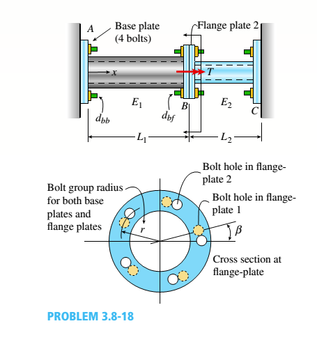
Two pipes {L, = 2.5 m and L, = 1.5 m) are joined al B by flange plales (thickness (, = 14 mm) with five bolts [dlt, = 13 mm] arranged in a circular pal tor n (see figure). Also, each pipe segment is atlaehed to a wall (at .1 and ( '. see figure! using a base plate Uh = 15 mm) and four bolts (dM, = 16 mm). All bolts are tightened until just snug. Assume £, = 110 GPa,E2 = 73 GPa,», = 0.33,andv, = 0.25. Neglect the self-weight of the pipes, and assume the pipes are in a stress-free stale initially. The cross-sectional areas of the pipes are At = 1500 mm: and A2 = (3/5)4. The ollter diameter of Pipe 1 is 60 mm. The outer diameter of Pipe 2 is equal to the inner diameter of Pipe 1. The bolt radius r = 64 mm for both base and flange plates.
(a)
If torque '/'is applied at .v = Lt. find an expression for reactive torques Iit and IL in terms of T.
(b)
Find the maximum load variable /'(i.e., Tmal) if allowable torsional stress in the two pipes is
Tall0* = 65 MPa-id Draw torsional moment iTMD i and torsional displacement (TDD) diagrams. Label all key ordinales. What is '/>.ll('.'
(d) Find mail, if allowable shear and bearing stresses in the base plate and flange bolts cannot be exceeded. Assume allowable stresses in shear an.: :vari:'.g I all bolls are r |Nill, = 45 MPa andtr MaK =90 MPa.
(e) Remove torque Tat x — L,. Now assume the flange-plate bolt holes are misaligned by some angle ß (see figure). Find the expressions for reactive torques Rx and R2 if the pipes are twisted to align the flange-plate bolt holes, bolts are then inserted, and the pipes released.
(f) What is the maximum permissible misalignment angle ß mix if allowable stresses in shear and bearing for all bolts [from part (d)] are not to be exceeded?
(a)
The reactive torque in terms of torque.
Answer to Problem 3.8.18P
The reactive torque at point (A) is =
The reactive torque at point (B) is =
Explanation of Solution
Given information:
Figure (1) shows the systematic diagram of the system:
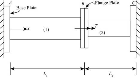
Figure-(1)
The length of first pipe is
Write the expression for cross sectional area of the pipe (1).
Here, the cross sectional area of the pipe (1) is
Write the expression for cross sectional area of the pipe (2).
Here, the cross sectional area of the pipe (2) is
Write the expression for the thickness of the pipe (1).
Here, the thickness of the pipe (1) is
Write the expression for the thickness of the pipe (2).
Here, the thickness of the pipe (2) is
Write the expression for polar moment of inertia for pipe (1).
Here, the polar moment of inertia of pipe (1) is
Write the expression for polar moment of inertia for pipe (2).
Here, the polar moment of inertia of pipe (2) is
Write the expression for modulus of rigidity for pipe (1).
Here, modulus of rigidity for pipe (1) is
Write the expression for modulus of rigidity for pipe (2).
Here, modulus of rigidity for pipe (2) is
Figure-(2) shows free body diagram of the system with internal torque and reactions at the end:
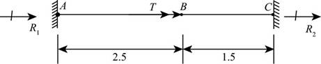
Figure-(2)
Write the expression of equilibrium condition for figure (2)
Here, the reaction torque acting at the point (A) is
Write the expression for torsional flexibility of pipe (1)
Here, the torsional rigidity of pipe (1) is
Write the expression for torsional flexibility of pipe (2)
Here, the torsional rigidity of pipe (1) is
Write the expression for angle of twist for pipe (1)
Here, the angle of twist for pipe (1) is
Write the expression for angle of twist for pipe (2)
Here, the angle of twist for pipe (1) is
Since, the angle of twist in pipe (1) and pipe (2) are opposite in direction
Substitute,
Calculation:
Substitute
Substitute
Substitute
Substitute
Substitute
Substitute
Substitute
Substitute
Substitute
Substitute
Substitute
Substitute
Conclusion:
The reactive torque at point (A) is
The reactive torque at point (B) is
(b)
The maximum load variable
Answer to Problem 3.8.18P
The maximum load variable
Explanation of Solution
Given information:
Permissible torsional stress in two pipes is
Write the expression for maximum load in pipe (1).
Here, maximum load in the pipe (1) is
Write the expression for maximum load in pipe (1).
Here, maximum load in the pipe (2) is
Write the expression for maximum load variable in pipe (1).
Here, the maximum load variable is
Calculation:
Substitute
Substitute
Since, the pipe (1) is greater, the maximum load variable in pipe (1).
Substitute
Conclusion:
The maximum load variable is =
(c)
The torsional moment diagrams.
The torsional displacement diagrams.
The maximum angle of twist.
Answer to Problem 3.8.18P
The maximum angle of twist is
Explanation of Solution
Given information:
Figure (3) shows torsional moment diagram and torsional displacement diagram for the given system.
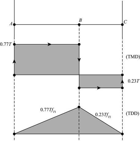
Figure-(3)
Write the expression for maximum angle of twist
Here, maximum angle of twist is =
Calculation:
Substitute
Conclusion:
The maximum angle of twist is =
(c)
The maximum torque for limiting value shear and bearing stress of base plate and flange bolts.
Answer to Problem 3.8.18P
The maximum torque for limiting value shear and bearing stress of base plate and flange bolts is =
Explanation of Solution
Given information:
The permissible shear stress for all bolts is
Write the expression for cross -sectional area of the base plate bolt.
Here, the cross-sectional area of the base plate bolt is
Write the expression for cross sectional area of the flange plate bolt.
Here, the cross-sectional area of the flange plate bolt is
Write the expression for maximum shear load in base plate bolt.
Here, the maximum shear load in base plate is
Here, the maximum shear load in flange plate is
Write the expression for area of the base plate bolt.
Here, the area of base plate bolt is
Write the expression for area of the flange plate bolt.
Here, the area of base plate bolt is
Write the expression for bearing load on base plate
Here, the maximum shear load in base plate is
Here, the maximum shear load in flange plate is
Calculation:
Substitute
Substitute
Substitute
Substitute
Substitute
Substitute
Substitute
Substitute
Conclusion:
The maximum torque for limiting value shear and bearing stress of base plate and flange bolts is =
Want to see more full solutions like this?
Chapter 3 Solutions
Mechanics of Materials (MindTap Course List)


- My ID#016948724 please solve this problems and show me every step clear to follow pleasearrow_forwardMy ID# 016948724arrow_forwardPlease do not use any AI tools to solve this question. I need a fully manual, step-by-step solution with clear explanations, as if it were done by a human tutor. No AI-generated responses, please.arrow_forward
- Please do not use any AI tools to solve this question. I need a fully manual, step-by-step solution with clear explanations, as if it were done by a human tutor. No AI-generated responses, please.arrow_forwardPlease do not use any AI tools to solve this question. I need a fully manual, step-by-step solution with clear explanations, as if it were done by a human tutor. No AI-generated responses, please.arrow_forward[Q2]: The cost information supplied by the cost accountant is as follows:Sales 20,00 units, $ 10 per unitCalculate the (a/ newsale guantity and (b) new selling price to earn the sameVariable cost $ 6 per unit, Fixed Cost $ 30,000, Profit $ 50,000profit ifi) Variable cost increases by $ 2 per unitil) Fixed cost increase by $ 10,000Ili) Variable cost increase by $ 1 per unit and fixed cost reduces by $ 10,000arrow_forward
- can you please help me perform Visual Inspection and Fractography of the attatched image: Preliminary examination to identify the fracture origin, suspected fatigue striation, and corrosion evidences.arrow_forwardcan you please help[ me conduct Causal Analysis (FTA) on the scenario attatched: FTA diagram which is a fault tree analysis diagram will be used to gain an overview of the entire path of failure from root cause to the top event (i.e., the swing’s detachment) and to identify interactions between misuse, material decay and inspection errors.arrow_forwardhi can you please help me in finding the stress intensity factor using a k-calcluator for the scenario attathced in the images.arrow_forward
 Mechanics of Materials (MindTap Course List)Mechanical EngineeringISBN:9781337093347Author:Barry J. Goodno, James M. GerePublisher:Cengage Learning