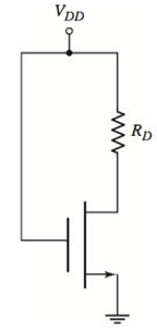
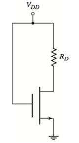
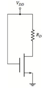
The transistor in the circuit in Figure P3.27 has parameters V T N = 0.8 V and K n = 0.25 mA/V 2 . Sketch the load line and plot the Q−point for (a) V D D = 4 V, R D = 1 k Ω and (b) V D D = 5 V, R D = 3 k Ω . What is the operating bias region for each condition? Figure P3.27
The transistor in the circuit in Figure P3.27 has parameters V T N = 0.8 V and K n = 0.25 mA/V 2 . Sketch the load line and plot the Q−point for (a) V D D = 4 V, R D = 1 k Ω and (b) V D D = 5 V, R D = 3 k Ω . What is the operating bias region for each condition? Figure P3.27
The transistor in the circuit in Figure P3.27 has parameters
V
T
N
=
0.8
V
and
K
n
=
0.25
mA/V
2
. Sketch the load line and plot the Q−point for (a)
V
D
D
=
4
V,
R
D
=
1
k
Ω
and (b)
V
D
D
=
5
V,
R
D
=
3
k
Ω
. What is the operating bias region for each condition?
Figure P3.27
(a)
Expert Solution
To determine
To sketch: A load line and labelQ -point.
To find: The region of operation of transistor.
Answer to Problem 3.27P
A load line along with Q -point is shown in Figure 1.
The transistor operates in triode region.
Explanation of Solution
Given Information:
The given circuit is shown below.
VTN=0.8V,Kn=0.25mAV2VDD=4V,RD=1kΩ
Calculation:
The value of VGS is:
VGS=VG−VSVGS=VDD−0VGS=4V
The value of VDS(sat) is:
VDS(sat)=VGS−VTNVDS(sat)=4−0.8VDS(sat)=3.2V
Applying Kirchhoff’s voltage in drain-source terminal:
A singl core cable of voltage 30 kv.
The diameter of Conductor is 3 cm.
The diameter of cable is 25 cm. This
cable has Two layer of insulator having
arelative permittivity 5-3 respectively
of
The ratio of
maximum electric stress
of
maximum electric stress
8
First layer to the
of second layer is 10 Find &
1- The thickness of each layers.
3-
The voltage of each
layers. §.
Layers
The saving in radius of cable if
another ungrading cable has the
Same maximum electric stress, Total
village, Conductor diameter of
grading cable.
66 KV sing care Cable has
a drameter of conductor of 3 cm.
The radius of cable is 10 cm.
This Cable house Two relative permmitivity
of insulation 6 and 4 respectively.
If The ratio of maximum electric stress
of first layer to the maximum eledric
streep & second layer is s
1- find the village & each layers.
2- Min- electric stress J Cable
3- Compare the voltage of ungrading
Cable has the same distance and
relectric stresses.
Prelab Information
1. Laboratory Preliminary Discussion
First-order Low-pass RC Filter Analysis
The first-order low-pass RC filter shown in figure 1 below represents all voltages and currents in the time domain. It is of course
possible to solve for all circuit voltages using time domain differential equation techniques, but it is more efficient to convert the
circuit to its s-domain equivalent as shown in figure 2 and apply Laplace transform techniques.
vs(t)
i₁(t)
+
R₁
ww
V₁(t)
12(t)
Lic(t)
Vout(t)
=
V2(t)
R₂
Vc(t)
C
Vc(t)
VR2(t)
= V2(t)
+
Vs(s)
Figure 1: A first-order low-pass RC filter represented in the time domain.
I₁(s)
R1
W
+
V₁(s)
V₂(s)
12(s)
Ic(s)
+
Vout(S)
==
Vc(s)
Vc(s)
Zc(s)
=
=
VR2(S)
V2(s)
Figure 2: A first-order low-pass RC filter represented in the s-domain.
Need a deep-dive on the concept behind this application? Look no further. Learn more about this topic, electrical-engineering and related others by exploring similar questions and additional content below.


 Introductory Circuit Analysis (13th Edition)Electrical EngineeringISBN:9780133923605Author:Robert L. BoylestadPublisher:PEARSON
 Delmar's Standard Textbook Of ElectricityElectrical EngineeringISBN:9781337900348Author:Stephen L. HermanPublisher:Cengage Learning
 Programmable Logic ControllersElectrical EngineeringISBN:9780073373843Author:Frank D. PetruzellaPublisher:McGraw-Hill Education
 Fundamentals of Electric CircuitsElectrical EngineeringISBN:9780078028229Author:Charles K Alexander, Matthew SadikuPublisher:McGraw-Hill Education
 Electric Circuits. (11th Edition)Electrical EngineeringISBN:9780134746968Author:James W. Nilsson, Susan RiedelPublisher:PEARSON
 Engineering ElectromagneticsElectrical EngineeringISBN:9780078028151Author:Hayt, William H. (william Hart), Jr, BUCK, John A.Publisher:Mcgraw-hill Education,