
Videos
(a) Determine a numerical value for each current and voltage (i1, v1, etc.) in the circuit of Fig. 3.64. (b) Calculate the power absorbed by each element and verify that they sum to zero.
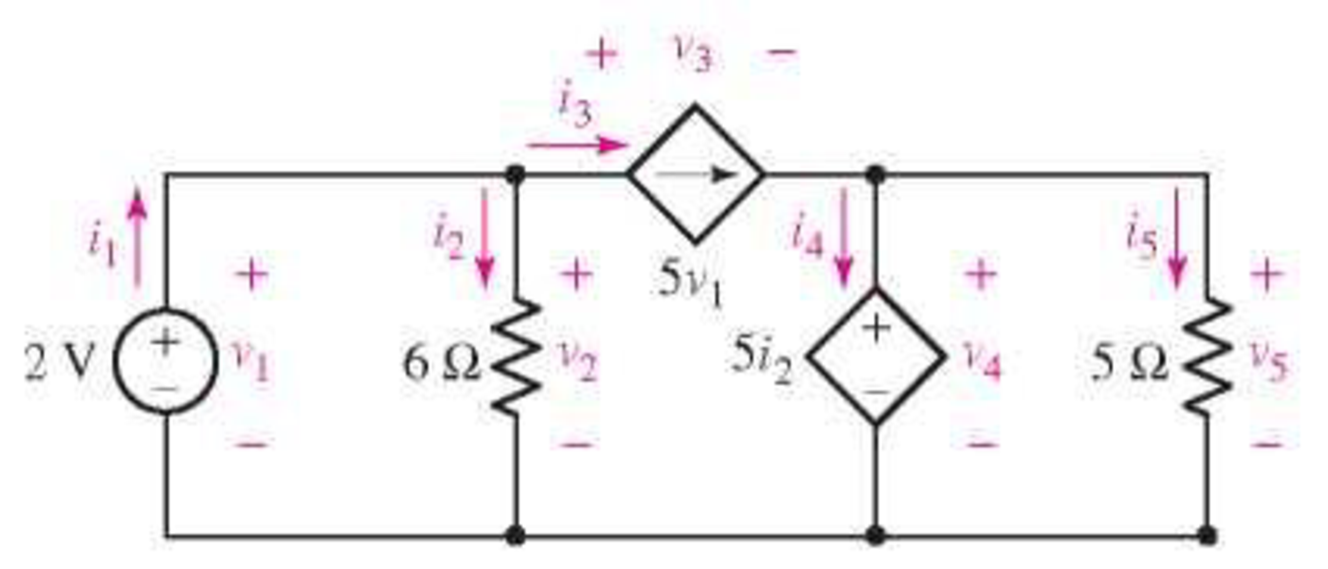
FIGURE 3.64
(a)
Find the value of current and voltage in the circuit.
Answer to Problem 23E
The current
The voltage
Explanation of Solution
Calculation:
The redrawn circuit is shown in Figure 1
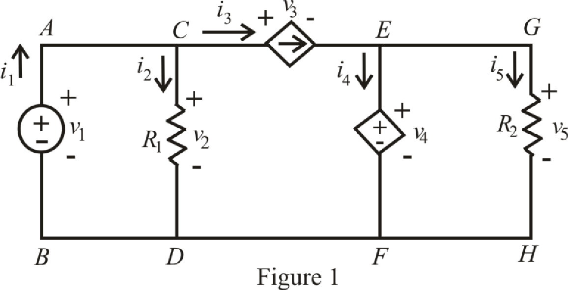
Refer to the Figure 1.
Since there is no voltage drop across branch
Here,
Refer to the Figure 1.
The expression for KCL at node
Here,
Refer to the Figure 1.
By ohm’s law the voltage across branch
Here,
Refer to the Figure 1
The expression for current
Refer to the Figure 1.
The expression for voltage
Here,
Refer to the Figure 1.
Since, the voltage across branch
Here,
By ohm’s law the voltage across branch is
The expression for KCL at node is
The expression for KVL across the loop
Refer to the Figure 1.
Substitute
Substitute
Rearrange for
Substitute 
Substitute
Substitute
Substitute
Substitute
Rearrange for
Substitute
Rearrange for
Substitute
Rearrange for
Conclusion:
Thus, the current
The voltage
(b)
Calculate the power absorbed by each element and verify total sum of power absorbed is zero.
Answer to Problem 23E
The power absorbed by independent voltage source is
The power absorbed by
The power absorbed by dependent current source is
The power absorbed by dependent voltage source is
The power absorbed by
Explanation of Solution
Formula used:
Refer to the Figure 1.
The expression for power supply by the voltage source from branch
Here,
The expression for power absorbed by resistance
The expression for power supply by the current dependent source from branch
The expression for power supply by the voltage dependent source from branch
The expression for power dissipate by the resistance
The expression for sum of total power absorbed in the circuit is,
Calculation:
Refer to the Figure 1.
Substitute
Substitute
Substitute
Substitute
Substitute
Substitute
Conclusion:
Thus, the power absorbed by independent voltage source is
The power absorbed by
The power absorbed by dependent current source is
The power absorbed by dependent voltage source is
The power absorbed by
Want to see more full solutions like this?
Chapter 3 Solutions
Loose Leaf for Engineering Circuit Analysis Format: Loose-leaf


- The part of machine level instruction, which tells the central processor what was to be done is: A. Address B. None of the above C. Operation code D. Operandarrow_forwardWhich of the following statement is TRUE? 1. In RISC processors, each instruction requires only two clock cycles to complete, resulting in consistent execution time 2. RISC has more transistors and fewer registers 3. RISC has more registers and fewer transistorsarrow_forwardDifferentiate between JFET and BJT.arrow_forward
- Give relation between αdc and βdc.arrow_forwardFind the power delivered across the 45 ohm resistorarrow_forwardA half-wave controlled rectifier is supplied by a 230 Vrms voltage source and has load resistance of 2502. Calculate the delay angle a that produces a load-absorbed power of 200W.arrow_forward
- not use ai pleasearrow_forwardFigure 1 shows a half-wave controlled rectifier which is supplied by a Vin = 120 Vrms voltage source. Assume that the load resistance is R = 10 2. Determine: a) The firing angle a of the thyristor to produce an average output voltage 50Vdc. Vin=Vmsinoot b) The average power Po absorbed by the load R. Figure 1 R = 1092arrow_forwardQ1. What is power dissipation in the Zener diode circuit given for a) RL=100 Ohm ? b) RL=∞arrow_forward
- The one-line diagram of an unloaded power system is shown below. Reactances of the two sections of transmission line are shown on the diagram. The generators and transformers are rated as follows: 20 MVA, 13.8 kV, X = 0.20 p.u Generator 1: Generator 2: Generator 3: 30 MVA, 18 kV, X = 0.20 p.u Transformer Ti: Transformer T2: 30 MVA, 20 kV, X = 0.20 p.u 25 MVA, 220Y/13.8A kV, X = 10% Three single-phase units each rated 10 MVA, 127/18 kV, X = 10% HT sides connected in wye Transformer T3: LT sides connected in delta 35 MVA, 220Y/22Y KV, X = 10% j80 Q j100 Q Line 1 Line 2 T₁ T₂ Draw the impedance diagram with all reactances marked in per unit. Choose a base of 50 MVA, 13.8 kV in the circuit of generator 1.arrow_forwardntotnarrow_forwardIn Fig.35 resistive loads, 1, 2, and 3, respectively, absorb 1200 W, 2400 W, and 3600 W. Calculate the current: a. In lines A and B. b. In the neutral conductors. c. In the HV line.arrow_forward
 Introductory Circuit Analysis (13th Edition)Electrical EngineeringISBN:9780133923605Author:Robert L. BoylestadPublisher:PEARSON
 Delmar's Standard Textbook Of ElectricityElectrical EngineeringISBN:9781337900348Author:Stephen L. HermanPublisher:Cengage Learning
 Programmable Logic ControllersElectrical EngineeringISBN:9780073373843Author:Frank D. PetruzellaPublisher:McGraw-Hill Education
 Fundamentals of Electric CircuitsElectrical EngineeringISBN:9780078028229Author:Charles K Alexander, Matthew SadikuPublisher:McGraw-Hill Education
 Electric Circuits. (11th Edition)Electrical EngineeringISBN:9780134746968Author:James W. Nilsson, Susan RiedelPublisher:PEARSON
 Engineering ElectromagneticsElectrical EngineeringISBN:9780078028151Author:Hayt, William H. (william Hart), Jr, BUCK, John A.Publisher:Mcgraw-hill Education,