
Loose Leaf for Engineering Circuit Analysis Format: Loose-leaf
9th Edition
ISBN: 9781259989452
Author: Hayt
Publisher: Mcgraw Hill Publishers
expand_more
expand_more
format_list_bulleted
Concept explainers
Videos
Textbook Question
Chapter 3.2, Problem 1P
3.1 (a) Count the number of branches and nodes in the circuit in Fig. 3.4. (b) If ix = 3 A and the 18 V source delivers 8 A of current, what is the value of RA? (Hint: You need Ohm’s law as well as KCL.)
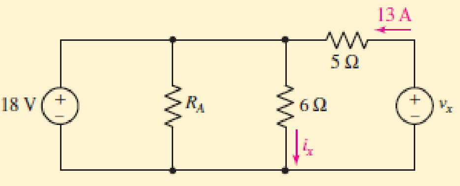
FIGURE 3.4
Expert Solution & Answer
Want to see the full answer?
Check out a sample textbook solution
Students have asked these similar questions
Semiconductor A has a band gap of 1eV, while semiconductor B has a band gap of 2eV. What is the
ration of the intrinsic carrier concentrations in the two materials (n₁A/NB) at 300 K. Assume any
differences in the carrier effective masses may be neglected.
c) The electron concentration in a piece of Si maintained at 300K under equilibrium conditions is
105/cm³. What is the hole concentration?
5. Represent the following system in state-space form. Write A, B, C and D clearly in
your answer.
d³y d²y
dt3
-
+5y=2u
dt²
Chapter 3 Solutions
Loose Leaf for Engineering Circuit Analysis Format: Loose-leaf
Ch. 3.2 - 3.1 (a) Count the number of branches and nodes in...Ch. 3.3 - Determine ix and vx in the circuit of Fig. 3.7....Ch. 3.3 - For the circuit of Fig. 3.9, if vR1=1V, determine...Ch. 3.3 - Determine vx in the circuit of Fig. 3.11.Ch. 3.4 - In the circuit of Fig. 3.12b, vs1 = 120 V, vs2 =...Ch. 3.4 - 3.6 In the circuit of Fig. 3.14, find the power...Ch. 3.5 - Determine v in the circuit of Fig. 3.16.Ch. 3.5 - For the single-node-pair circuit of Fig. 3.18,...Ch. 3.6 - Determine the current i in the circuit of Fig....Ch. 3.6 - Determine the voltage v in the circuit of Fig....
Ch. 3.6 - Determine whether the circuit of Fig. 3.25...Ch. 3.7 - 3.12 Determine a single-value equivalent...Ch. 3.7 - 3.13 Determine i in the circuit of Fig. 3.29....Ch. 3.7 - Determine v in the circuit of Fig. 3.31 by first...Ch. 3.7 - 3.15 For the circuit of Fig. 3.33, calculate the...Ch. 3.8 - 3.16 Use voltage division to determine vx in the...Ch. 3.8 - In the circuit of Fig. 3.40, use resistance...Ch. 3 - Referring to the circuit depicted in Fig. 3.45,...Ch. 3 - Referring to the circuit depicted in Fig. 3.46,...Ch. 3 - For the circuit of Fig. 3.47: (a) Count the number...Ch. 3 - For the circuit of Fig. 3.47: (a) Count the number...Ch. 3 - Refer to the circuit of Fig. 3.48, and answer the...Ch. 3 - A local restaurant has a neon sign constructed...Ch. 3 - Referring to the single-node diagram of Fig. 3.50,...Ch. 3 - Determine the current labeled I in each of the...Ch. 3 - In the circuit shown in Fig. 3.52, the resistor...Ch. 3 - The circuit of Fig. 3.53 represents a system...Ch. 3 - In the circuit depicted in Fig. 3.54, ix is...Ch. 3 - For the circuit of Fig. 3.55 (which employs a...Ch. 3 - Determine the current labeled I3 in the circuit of...Ch. 3 - Study the circuit depicted in Fig. 3.57, and...Ch. 3 - Prob. 15ECh. 3 - For the circuit of Fig. 3.58: (a) Determine the...Ch. 3 - For each of the circuits in Fig. 3.59, determine...Ch. 3 - Use KVL to obtain a numerical value for the...Ch. 3 - Prob. 19ECh. 3 - In the circuit of Fig. 3.55, calculate the voltage...Ch. 3 - Determine the value of vx as labeled in the...Ch. 3 - Consider the simple circuit shown in Fig. 3.63....Ch. 3 - (a) Determine a numerical value for each current...Ch. 3 - The circuit shown in Fig. 3.65 includes a device...Ch. 3 - The circuit of Fig. 3.12b is constructed with the...Ch. 3 - Obtain a numerical value for the power absorbed by...Ch. 3 - Compute the power absorbed by each element of the...Ch. 3 - Compute the power absorbed by each element in the...Ch. 3 - Kirchhoffs laws apply whether or not Ohms law...Ch. 3 - Referring to the circuit of Fig. 3.70, (a)...Ch. 3 - Determine a value for the voltage v as labeled in...Ch. 3 - Referring to the circuit depicted in Fig. 3.72,...Ch. 3 - Determine the voltage v as labeled in Fig. 3.73,...Ch. 3 - Although drawn so that it may not appear obvious...Ch. 3 - Determine the numerical value for veq in Fig....Ch. 3 - Determine the numerical value for ieq in Fig....Ch. 3 - For the circuit presented in Fig. 3.76. determine...Ch. 3 - Determine the value of v1 required to obtain a...Ch. 3 - (a) For the circuit of Fig. 3.78, determine the...Ch. 3 - What value of IS in the circuit of Fig. 3.79 will...Ch. 3 - (a) Determine the values for IX and VY in the...Ch. 3 - Determine the equivalent resistance of each of the...Ch. 3 - For each network depicted in Fig. 3.82, determine...Ch. 3 - (a) Simplify the circuit of Fig. 3.83 as much as...Ch. 3 - (a) Simplify the circuit of Fig. 3.84, using...Ch. 3 - Making appropriate use of resistor combination...Ch. 3 - Calculate the voltage labeled vx in the circuit of...Ch. 3 - Determine the power absorbed by the 15 resistor...Ch. 3 - Calculate the equivalent resistance Req of the...Ch. 3 - Show how to combine four 100 resistors to obtain...Ch. 3 - Prob. 51ECh. 3 - Prob. 52ECh. 3 - Prob. 53ECh. 3 - Prob. 54ECh. 3 - Prob. 55ECh. 3 - Prob. 56ECh. 3 - Prob. 57ECh. 3 - Prob. 58ECh. 3 - Prob. 59ECh. 3 - Prob. 60ECh. 3 - With regard to the circuit shown in Fig. 3.98,...Ch. 3 - Delete the leftmost 10 resistor in the circuit of...Ch. 3 - Consider the seven-element circuit depicted in...
Additional Engineering Textbook Solutions
Find more solutions based on key concepts
This optional Google account security feature sends you a message with a code that you must enter, in addition ...
SURVEY OF OPERATING SYSTEMS
1.2 Explain the difference between geodetic and plane
surveys,
Elementary Surveying: An Introduction To Geomatics (15th Edition)
How does a computers main memory differ from its auxiliary memory?
Java: An Introduction to Problem Solving and Programming (8th Edition)
How is the hydrodynamic entry length defined for flow in a pipe? Is the entry length longer in laminar or turbu...
Fluid Mechanics: Fundamentals and Applications
Comprehension Check 7-14
The power absorbed by a resistor can be given by P = I2R, where P is power in units of...
Thinking Like an Engineer: An Active Learning Approach (4th Edition)
CONCEPT QUESTIONS
15.CQ3 The ball rolls without slipping on the fixed surface as shown. What is the direction ...
Vector Mechanics for Engineers: Statics and Dynamics
Knowledge Booster


Learn more about
Need a deep-dive on the concept behind this application? Look no further. Learn more about this topic, electrical-engineering and related others by exploring similar questions and additional content below.Similar questions
- 3. Find the transfer function H(s) and frequency response H (w) of the following system whose differential equation is given by d¹y d³y +3. dy +5 dt4 dt3 dt - d²u du 4y = - 5 dt² dtarrow_forward1. Consider a plant that you want to control. The input u(t) and output y(t) of the plant are related by y(t) = 7 u(t) + w(t) where w(t) is an additive disturbance at the output which is bounded by -0.5 w(t) ≤0.5 for all time t. You want to build a controller so that the output follows a constant reference signal r(t) = where -15 ≤≤ 15. You will consider both open-loop and closed-loop for this problem. a) Sketch the block diagram of the plant. b) Please build an open-loop controller that sets the output to 7, assuming the disturbance is ignored. Please show your controller both as an equation and a block diagram. c) Say that you use the open-loop controller in part b, but now the disturbance w(t) is present. What is the maximum possible magnitude of error in the output for the reference signal? Suppose you have designed a feedback control for the plant where the controller has the form u(t) = K(r(t) − y(t)). Here K is the gain constant of the controller that you will design. d) Please…arrow_forward2. Suppose the Laplace transform of a causal signal x(t) is given by s² +2 X(s) = S³ + 1 Using the lookup tables for standard Laplace transforms and the Laplace transform properties, find the Laplace transforms of the following signals. You do not need to simplify the expressions. a) x₁(t) = e² x(t) + 38(t − 1) − (t − 2)² u(t − 2) b) x2(t) = x(2t - 1) + et u(t − 2)arrow_forward
- Please explain in detail the steps to solve this. Thank youarrow_forward6. Answer the following questions. Take help from ChatGPT to answer these questions (if you need). But write the answers briefly using your own words with no more than two sentences and make sure you check whether ChatGPT is giving you the appropriate answers in our context. a) What is the difference between a regulator and a servo system? Which is harder to build? b) What are the advantages and drawbacks of manual control systems over automatic ones? c) Does transfer exist for the non-linear systems? d) Explain the convolution property of the Laplace transform. e) What are the advantages of using state-space representation?arrow_forward4. Find the differential equation of the following system whose transfer function is given by S+3 H(s) = s3 +3s+2arrow_forward
- Preliminary Laboratory (Prelab) Work Complete the following tasks in the space provided below for the circuit shown in Figure 2. 1. Use voltage division to compute the phasor voltages VR and Vc assuming nominal values of R = 1000[2], C = 0.01[u], and a cosinusoidal time-domain source voltage signal given by equation 5 below. Voltage division must be used to receive any credit. (10 points) equation (5) Vs(t) = VRMSCOS(ct + 0) = 5cos(@t + 0) = 5cos(62832t + 0) = 5cos(62832t) [V] =VRMSCOS(2лft + 0) = 5cos[2л(10000)t + 0] = 5cos[2л(10000)t] [V] 2. Compute the phasor current, Is. (3 points) 3. Calculate the complex power, S, active power, P, and reactive power, Q, for the circuit. (4 points) 4. Construct the phasor diagram for the circuit, and show mathematically that the phasor (vector) sum of the phasor voltages VR and Vc is equal to Vs. (3 points) Agilent 33210A (BECC4242) or Vs Keysight 33500B (BECC4261) Function Generators Is R w + VR Vc + + Zc V out =Vc Figure 2: RC circuit connected…arrow_forwardPlease explain in detail. My answer for the first question is 15/2. I am more confused about how to do the graphing part and figure how long it will take to reach its final value. Thank you, I will like this.arrow_forwardThis is the 3rd time i'm asking this. SOLVE THIS AND FIND V0 , the last answer i was given is -2V which is not even one of the listed options. the listed options are: 12V,4V,24V,6V. first answer given to me was 4V but after i simulated on ltspice albeit i'm not sure if i simulated correct i got a different answer and when i solved it myself i got a different answer. this is my last remaining question. PLEASE SOLVE CORRECTLY AND PROPERLY. NODAL ANALYSIS IS BEST TO USE HERE. IT IS AN IDEAL OP-AMP. SIMULATE USING LTSPICE AND GIVE ME FINAL ANSWER IF POSSIBLE AS THAT IS ALL I CARE ABOUT NOT THE PROCESS. THANK YOU. WILL UPVOTE CORRECT ANSWER, but downvote wrong answer.arrow_forward
- Find the exact value of V0. This question was already asked here and the answer was 4V i solved it myself and got a different answer and when i simulated it i also got a different answer.But i might be wrong. so please solve this for me and IF POSSIBLE simulate it so we can be 100% sure that the answer is correct as it's very important that i understand where i went wrong.arrow_forwardFind load flow Solution 1.2 20 Z12 = 0.01+jo.03 in Z₁4=0.02+0.04 и а 9.01+10.03 0.02+0.04 0.01+0.03 58-1 Vek 1.05 100 MVA Pe=230 MW 150 MW w 140 MW 01012 +0.035 80 M√ar 723=0.01+0.03 90 mvare Z34 = 0.012+ 10.035arrow_forwardSD = 100 MVA 1.12° 150mw ← 0.01+0.03 10.02 -0.04 Too M P = 250 MW 0.02+0.04 0.012 jo.03 $ (V3)=1.05 P.4 -03 = = 200 MW 212=0.01+10.03 Zzze 0.02 +10.04 214=0.02+10.04 Z34 = 0.012+10.03arrow_forward
arrow_back_ios
SEE MORE QUESTIONS
arrow_forward_ios
Recommended textbooks for you
 Introductory Circuit Analysis (13th Edition)Electrical EngineeringISBN:9780133923605Author:Robert L. BoylestadPublisher:PEARSON
 Delmar's Standard Textbook Of ElectricityElectrical EngineeringISBN:9781337900348Author:Stephen L. HermanPublisher:Cengage Learning
 Programmable Logic ControllersElectrical EngineeringISBN:9780073373843Author:Frank D. PetruzellaPublisher:McGraw-Hill Education
 Fundamentals of Electric CircuitsElectrical EngineeringISBN:9780078028229Author:Charles K Alexander, Matthew SadikuPublisher:McGraw-Hill Education
 Electric Circuits. (11th Edition)Electrical EngineeringISBN:9780134746968Author:James W. Nilsson, Susan RiedelPublisher:PEARSON
 Engineering ElectromagneticsElectrical EngineeringISBN:9780078028151Author:Hayt, William H. (william Hart), Jr, BUCK, John A.Publisher:Mcgraw-hill Education,
Introductory Circuit Analysis (13th Edition)
Electrical Engineering
ISBN:9780133923605
Author:Robert L. Boylestad
Publisher:PEARSON
Delmar's Standard Textbook Of Electricity
Electrical Engineering
ISBN:9781337900348
Author:Stephen L. Herman
Publisher:Cengage Learning
Programmable Logic Controllers
Electrical Engineering
ISBN:9780073373843
Author:Frank D. Petruzella
Publisher:McGraw-Hill Education
Fundamentals of Electric Circuits
Electrical Engineering
ISBN:9780078028229
Author:Charles K Alexander, Matthew Sadiku
Publisher:McGraw-Hill Education
Electric Circuits. (11th Edition)
Electrical Engineering
ISBN:9780134746968
Author:James W. Nilsson, Susan Riedel
Publisher:PEARSON
Engineering Electromagnetics
Electrical Engineering
ISBN:9780078028151
Author:Hayt, William H. (william Hart), Jr, BUCK, John A.
Publisher:Mcgraw-hill Education,
Thevenin's Theorem; Author: Neso Academy;https://www.youtube.com/watch?v=veAFVTIpKyM;License: Standard YouTube License, CC-BY