
Loose Leaf for Engineering Circuit Analysis Format: Loose-leaf
9th Edition
ISBN: 9781259989452
Author: Hayt
Publisher: Mcgraw Hill Publishers
expand_more
expand_more
format_list_bulleted
Videos
Textbook Question
Chapter 3, Problem 18E
Use KVL to obtain a numerical value for the current labeled i in each circuit
depicted in Fig. 3.60.
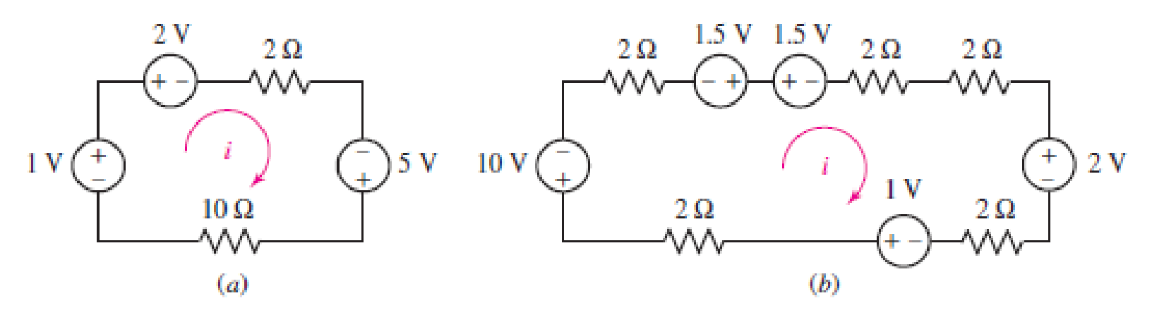
■ FIGURE 3.60
Expert Solution & Answer
Want to see the full answer?
Check out a sample textbook solution
Students have asked these similar questions
Consider the following transformer circuit assuming an ideal transformer. In this circuit
the signal generator will provide a 10-Volt peak-to-peak sinusoidal signal at a frequency
of 1.0 kHz. Assume that L₁ = 0.65 H, L2 = 0.00492 H (=4.92 mH) and that the coupling
constant = 0.99925.
+
VG1(
R1 1k
N1:N2
11.5:1
12
V1 N1
N2
V2
R2 8.2
1) Find the following using the theory presented in the prelab reading:
a) Start with Equations (2) of the prelab reading and show that the input impedance
to an ideal transformer is given by the equation for Z1 (=V1/11) in Equations (4) of
the prelab reading.
Equations (2) are: V₁ = joLI₁ + jœMI₂ and V₂ = j@MI₁ +j@L₂I₂
The equation for the input impedance is: Z₁ = 1½ = jwL₁ +
(WM)²
jwL₂+ZL
b) Assuming that Z is a real impedance, find the equations for the real and
imaginary parts of Z1.
c) Use your equations from part (b) to calculate the value of the input impedance
(Z) at an operating frequency of 200 Hz. Assume that the load impedance is 8.2
Ohms…
Use: R1 = 1.5K, R2 = 5K, R3 = 1K, R4 = 2K, R5 = 2K, R6 = 1K.
40%: Find the value for Vs (in V) such as IR2 = 1mA.
40%: Find the voltage VD.
20%: simulate the circuit in Falstad (attach the link).
A
1,5k
B
R1
Vs
L
5k
P2
R2
R6
E
C
R3
С
IR2= 1mA
D
H4
R4
2k
2k
R5
The joint pdf of random variables X=1, 2 and Y=1,2,3 is
Y
P(X,Y)= X [0.105
0.2
0.15]
0.151
0.18
Chapter 3 Solutions
Loose Leaf for Engineering Circuit Analysis Format: Loose-leaf
Ch. 3.2 - 3.1 (a) Count the number of branches and nodes in...Ch. 3.3 - Determine ix and vx in the circuit of Fig. 3.7....Ch. 3.3 - For the circuit of Fig. 3.9, if vR1=1V, determine...Ch. 3.3 - Determine vx in the circuit of Fig. 3.11.Ch. 3.4 - In the circuit of Fig. 3.12b, vs1 = 120 V, vs2 =...Ch. 3.4 - 3.6 In the circuit of Fig. 3.14, find the power...Ch. 3.5 - Determine v in the circuit of Fig. 3.16.Ch. 3.5 - For the single-node-pair circuit of Fig. 3.18,...Ch. 3.6 - Determine the current i in the circuit of Fig....Ch. 3.6 - Determine the voltage v in the circuit of Fig....
Ch. 3.6 - Determine whether the circuit of Fig. 3.25...Ch. 3.7 - 3.12 Determine a single-value equivalent...Ch. 3.7 - 3.13 Determine i in the circuit of Fig. 3.29....Ch. 3.7 - Determine v in the circuit of Fig. 3.31 by first...Ch. 3.7 - 3.15 For the circuit of Fig. 3.33, calculate the...Ch. 3.8 - 3.16 Use voltage division to determine vx in the...Ch. 3.8 - In the circuit of Fig. 3.40, use resistance...Ch. 3 - Referring to the circuit depicted in Fig. 3.45,...Ch. 3 - Referring to the circuit depicted in Fig. 3.46,...Ch. 3 - For the circuit of Fig. 3.47: (a) Count the number...Ch. 3 - For the circuit of Fig. 3.47: (a) Count the number...Ch. 3 - Refer to the circuit of Fig. 3.48, and answer the...Ch. 3 - A local restaurant has a neon sign constructed...Ch. 3 - Referring to the single-node diagram of Fig. 3.50,...Ch. 3 - Determine the current labeled I in each of the...Ch. 3 - In the circuit shown in Fig. 3.52, the resistor...Ch. 3 - The circuit of Fig. 3.53 represents a system...Ch. 3 - In the circuit depicted in Fig. 3.54, ix is...Ch. 3 - For the circuit of Fig. 3.55 (which employs a...Ch. 3 - Determine the current labeled I3 in the circuit of...Ch. 3 - Study the circuit depicted in Fig. 3.57, and...Ch. 3 - Prob. 15ECh. 3 - For the circuit of Fig. 3.58: (a) Determine the...Ch. 3 - For each of the circuits in Fig. 3.59, determine...Ch. 3 - Use KVL to obtain a numerical value for the...Ch. 3 - Prob. 19ECh. 3 - In the circuit of Fig. 3.55, calculate the voltage...Ch. 3 - Determine the value of vx as labeled in the...Ch. 3 - Consider the simple circuit shown in Fig. 3.63....Ch. 3 - (a) Determine a numerical value for each current...Ch. 3 - The circuit shown in Fig. 3.65 includes a device...Ch. 3 - The circuit of Fig. 3.12b is constructed with the...Ch. 3 - Obtain a numerical value for the power absorbed by...Ch. 3 - Compute the power absorbed by each element of the...Ch. 3 - Compute the power absorbed by each element in the...Ch. 3 - Kirchhoffs laws apply whether or not Ohms law...Ch. 3 - Referring to the circuit of Fig. 3.70, (a)...Ch. 3 - Determine a value for the voltage v as labeled in...Ch. 3 - Referring to the circuit depicted in Fig. 3.72,...Ch. 3 - Determine the voltage v as labeled in Fig. 3.73,...Ch. 3 - Although drawn so that it may not appear obvious...Ch. 3 - Determine the numerical value for veq in Fig....Ch. 3 - Determine the numerical value for ieq in Fig....Ch. 3 - For the circuit presented in Fig. 3.76. determine...Ch. 3 - Determine the value of v1 required to obtain a...Ch. 3 - (a) For the circuit of Fig. 3.78, determine the...Ch. 3 - What value of IS in the circuit of Fig. 3.79 will...Ch. 3 - (a) Determine the values for IX and VY in the...Ch. 3 - Determine the equivalent resistance of each of the...Ch. 3 - For each network depicted in Fig. 3.82, determine...Ch. 3 - (a) Simplify the circuit of Fig. 3.83 as much as...Ch. 3 - (a) Simplify the circuit of Fig. 3.84, using...Ch. 3 - Making appropriate use of resistor combination...Ch. 3 - Calculate the voltage labeled vx in the circuit of...Ch. 3 - Determine the power absorbed by the 15 resistor...Ch. 3 - Calculate the equivalent resistance Req of the...Ch. 3 - Show how to combine four 100 resistors to obtain...Ch. 3 - Prob. 51ECh. 3 - Prob. 52ECh. 3 - Prob. 53ECh. 3 - Prob. 54ECh. 3 - Prob. 55ECh. 3 - Prob. 56ECh. 3 - Prob. 57ECh. 3 - Prob. 58ECh. 3 - Prob. 59ECh. 3 - Prob. 60ECh. 3 - With regard to the circuit shown in Fig. 3.98,...Ch. 3 - Delete the leftmost 10 resistor in the circuit of...Ch. 3 - Consider the seven-element circuit depicted in...
Additional Engineering Textbook Solutions
Find more solutions based on key concepts
What types of coolant are used in vehicles?
Automotive Technology: Principles, Diagnosis, And Service (6th Edition) (halderman Automotive Series)
Write a summary list of the problem-solving steps identified in the chapter, using your own words.
BASIC BIOMECHANICS
Why is the study of database technology important?
Database Concepts (8th Edition)
Assume a telephone signal travels through a cable at two-thirds the speed of light. How long does it take the s...
Electric Circuits. (11th Edition)
17–1C A high-speed aircraft is cruising in still air. How does the temperature of air at the nose of the aircra...
Thermodynamics: An Engineering Approach
How are relationships between tables expressed in a relational database?
Modern Database Management
Knowledge Booster


Learn more about
Need a deep-dive on the concept behind this application? Look no further. Learn more about this topic, electrical-engineering and related others by exploring similar questions and additional content below.Similar questions
- Find the eigenvalues and the corresponding eigen vectors of the following matrix: -5 A = [ 21 -7 4]arrow_forward+ 2) Acircuit is given as shown. (a) Find and label the circuit nodes (6) Determine voltages V₁, V2, V3 and Vy 4V C/E 노동 + 051 V4 + C/E + 3V- + /E5V 1 av + C E uk لا + V3C/E CIE + E6V -arrow_forwardConsider the following transformer circuit assuming an ideal transformer. In this circuit the signal generator will provide a 10-Volt peak-to-peak sinusoidal signal at a frequency of 1.0 kHz. Assume that L₁ = 0.65 H, L2 = 0.00492 H (=4.92 mH) and that the coupling constant = 0.99925. + VG1( R1 1k N1:N2 11.5:1 12 V1 N1 N2 V2 R2 8.2 1) Find the following using the theory presented in the prelab reading: a) Start with Equations (2) of the prelab reading and show that the input impedance to an ideal transformer is given by the equation for Z1 (=V1/11) in Equations (4) of the prelab reading. Equations (2) are: V₁ = joLI₁ + jœMI₂ and V₂ = j@MI₁ +j@L₂I₂ The equation for the input impedance is: Z₁ = 1½ = jwL₁ + (WM)² jwL₂+ZL b) Assuming that Z is a real impedance, find the equations for the real and imaginary parts of Z1. c) Use your equations from part (b) to calculate the value of the input impedance (Z) at an operating frequency of 200 Hz. Assume that the load impedance is 8.2 Ohms…arrow_forward
- HANDWRITTEN SOLUTION PLEASE NOT USING AIarrow_forwardFor the network of Fig. 7.93, determine: a. ID, and VGS₂- 18 V b. Vps and Vs. Shockley's equation, VGS ID= Vp) ID Vos V 1- VIDSS VGSQ VG = R₂VDD R₁ + R2 VGS VG-IDRS VDS VDD-ID(RD + Rs) (a) ID = 9 mA, VGS₁ = 0.5 V (b) VDs = 7.69 V, Vs = -0.5 V • 2.2 ΚΩ Dss = 8 mA Vp=-8V • 0.39 ΚΩ 8-4 V FIG. 7.93arrow_forwardHANDWRITTEN SOLUTION NOT USING AIarrow_forward
- Find the Eigenvalues and the corresponding Eigenvectors. 4 = [3³/2 0] =b A ยarrow_forward- Find Eigenvalues and Eigenvectors for the following matrices: A = 12arrow_forward4-9 A separate excited dc generator turning at 1400 r/min produces an induced voltage of 127 V. The armature resistance is 2 and the machine delivers a current of 12 A. Calculate a. the terminal voltage [V] b. the heat dissipated in the armature [W] c. the braking torque exerted by the armature [N-m]arrow_forward
- 1. Label the x, y, z coordinates for each frame. 2. Compute the homogeneous transformation matrices H between frames 0, 1, 2, and end- effector. 3. Use your MATLAB function to compute H°3. 01 d₁ d 02 d3arrow_forward4-8 Explain the difference between shunt, com- pound, and differential compound generators a. as to construction b. as to electrical propertiesarrow_forwardFor the following circuit bellow, given VS is 1.3 V. What is the value of VL? Is it possible to determine the vlaues of RS or RL. If so what are their values.arrow_forward
arrow_back_ios
SEE MORE QUESTIONS
arrow_forward_ios
Recommended textbooks for you
 Introductory Circuit Analysis (13th Edition)Electrical EngineeringISBN:9780133923605Author:Robert L. BoylestadPublisher:PEARSON
 Delmar's Standard Textbook Of ElectricityElectrical EngineeringISBN:9781337900348Author:Stephen L. HermanPublisher:Cengage Learning
 Programmable Logic ControllersElectrical EngineeringISBN:9780073373843Author:Frank D. PetruzellaPublisher:McGraw-Hill Education
 Fundamentals of Electric CircuitsElectrical EngineeringISBN:9780078028229Author:Charles K Alexander, Matthew SadikuPublisher:McGraw-Hill Education
 Electric Circuits. (11th Edition)Electrical EngineeringISBN:9780134746968Author:James W. Nilsson, Susan RiedelPublisher:PEARSON
 Engineering ElectromagneticsElectrical EngineeringISBN:9780078028151Author:Hayt, William H. (william Hart), Jr, BUCK, John A.Publisher:Mcgraw-hill Education,
Introductory Circuit Analysis (13th Edition)
Electrical Engineering
ISBN:9780133923605
Author:Robert L. Boylestad
Publisher:PEARSON
Delmar's Standard Textbook Of Electricity
Electrical Engineering
ISBN:9781337900348
Author:Stephen L. Herman
Publisher:Cengage Learning
Programmable Logic Controllers
Electrical Engineering
ISBN:9780073373843
Author:Frank D. Petruzella
Publisher:McGraw-Hill Education
Fundamentals of Electric Circuits
Electrical Engineering
ISBN:9780078028229
Author:Charles K Alexander, Matthew Sadiku
Publisher:McGraw-Hill Education
Electric Circuits. (11th Edition)
Electrical Engineering
ISBN:9780134746968
Author:James W. Nilsson, Susan Riedel
Publisher:PEARSON
Engineering Electromagnetics
Electrical Engineering
ISBN:9780078028151
Author:Hayt, William H. (william Hart), Jr, BUCK, John A.
Publisher:Mcgraw-hill Education,
[1.2] 8086 Microprocessor Architecture; Author: ThinkX Academy;https://www.youtube.com/watch?v=XX9rDGTBGgQ;License: Standard Youtube License