
Loose Leaf for Engineering Circuit Analysis Format: Loose-leaf
9th Edition
ISBN: 9781259989452
Author: Hayt
Publisher: Mcgraw Hill Publishers
expand_more
expand_more
format_list_bulleted
Videos
Textbook Question
Chapter 3, Problem 17E
For each of the circuits in Fig. 3.59, determine the voltage vx and the current ix.
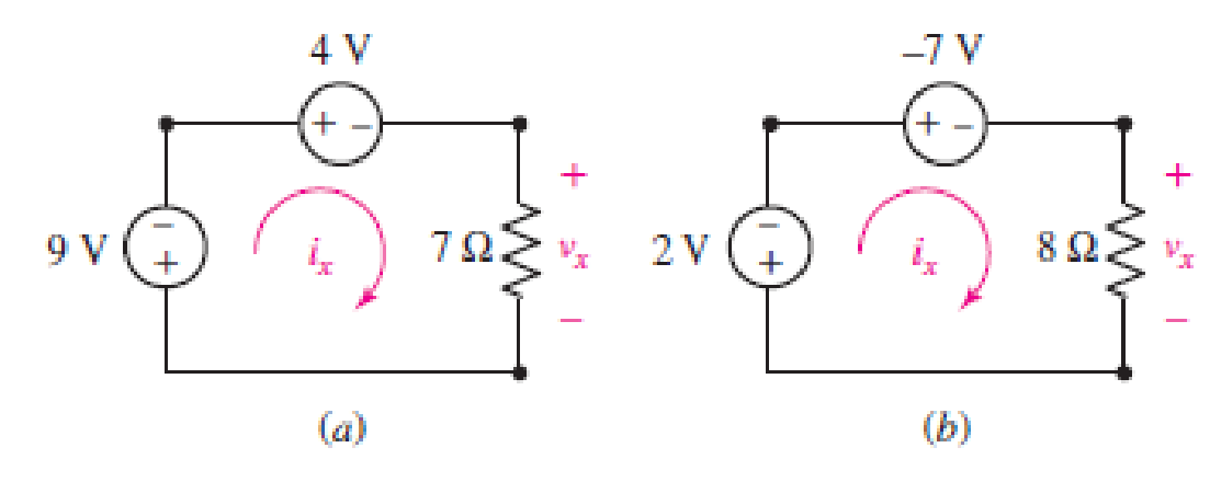
■ FIGURE 3.59
Expert Solution & Answer
Want to see the full answer?
Check out a sample textbook solution
Students have asked these similar questions
Only expert should attempt this questions, handwritten solution only
Please show formula used and steps as I will study them
Question One
R
C
ww
(t)T
Figure 2: R-C Circuit
A series R-C circuit in figure 2, has a step input voltage applied to it. Use Laplace transforms
to determine expressions for
(a) Current, i(t) flowing in the circuit, given that when t = Os, i=0A [12 marks]
(b) Use the expression obtained in (a), calculate the current i(t) flowing in the circuit,
when V = 15volts, R = 50, C=1F, t = 1sec
[2 marks]
Chapter 3 Solutions
Loose Leaf for Engineering Circuit Analysis Format: Loose-leaf
Ch. 3.2 - 3.1 (a) Count the number of branches and nodes in...Ch. 3.3 - Determine ix and vx in the circuit of Fig. 3.7....Ch. 3.3 - For the circuit of Fig. 3.9, if vR1=1V, determine...Ch. 3.3 - Determine vx in the circuit of Fig. 3.11.Ch. 3.4 - In the circuit of Fig. 3.12b, vs1 = 120 V, vs2 =...Ch. 3.4 - 3.6 In the circuit of Fig. 3.14, find the power...Ch. 3.5 - Determine v in the circuit of Fig. 3.16.Ch. 3.5 - For the single-node-pair circuit of Fig. 3.18,...Ch. 3.6 - Determine the current i in the circuit of Fig....Ch. 3.6 - Determine the voltage v in the circuit of Fig....
Ch. 3.6 - Determine whether the circuit of Fig. 3.25...Ch. 3.7 - 3.12 Determine a single-value equivalent...Ch. 3.7 - 3.13 Determine i in the circuit of Fig. 3.29....Ch. 3.7 - Determine v in the circuit of Fig. 3.31 by first...Ch. 3.7 - 3.15 For the circuit of Fig. 3.33, calculate the...Ch. 3.8 - 3.16 Use voltage division to determine vx in the...Ch. 3.8 - In the circuit of Fig. 3.40, use resistance...Ch. 3 - Referring to the circuit depicted in Fig. 3.45,...Ch. 3 - Referring to the circuit depicted in Fig. 3.46,...Ch. 3 - For the circuit of Fig. 3.47: (a) Count the number...Ch. 3 - For the circuit of Fig. 3.47: (a) Count the number...Ch. 3 - Refer to the circuit of Fig. 3.48, and answer the...Ch. 3 - A local restaurant has a neon sign constructed...Ch. 3 - Referring to the single-node diagram of Fig. 3.50,...Ch. 3 - Determine the current labeled I in each of the...Ch. 3 - In the circuit shown in Fig. 3.52, the resistor...Ch. 3 - The circuit of Fig. 3.53 represents a system...Ch. 3 - In the circuit depicted in Fig. 3.54, ix is...Ch. 3 - For the circuit of Fig. 3.55 (which employs a...Ch. 3 - Determine the current labeled I3 in the circuit of...Ch. 3 - Study the circuit depicted in Fig. 3.57, and...Ch. 3 - Prob. 15ECh. 3 - For the circuit of Fig. 3.58: (a) Determine the...Ch. 3 - For each of the circuits in Fig. 3.59, determine...Ch. 3 - Use KVL to obtain a numerical value for the...Ch. 3 - Prob. 19ECh. 3 - In the circuit of Fig. 3.55, calculate the voltage...Ch. 3 - Determine the value of vx as labeled in the...Ch. 3 - Consider the simple circuit shown in Fig. 3.63....Ch. 3 - (a) Determine a numerical value for each current...Ch. 3 - The circuit shown in Fig. 3.65 includes a device...Ch. 3 - The circuit of Fig. 3.12b is constructed with the...Ch. 3 - Obtain a numerical value for the power absorbed by...Ch. 3 - Compute the power absorbed by each element of the...Ch. 3 - Compute the power absorbed by each element in the...Ch. 3 - Kirchhoffs laws apply whether or not Ohms law...Ch. 3 - Referring to the circuit of Fig. 3.70, (a)...Ch. 3 - Determine a value for the voltage v as labeled in...Ch. 3 - Referring to the circuit depicted in Fig. 3.72,...Ch. 3 - Determine the voltage v as labeled in Fig. 3.73,...Ch. 3 - Although drawn so that it may not appear obvious...Ch. 3 - Determine the numerical value for veq in Fig....Ch. 3 - Determine the numerical value for ieq in Fig....Ch. 3 - For the circuit presented in Fig. 3.76. determine...Ch. 3 - Determine the value of v1 required to obtain a...Ch. 3 - (a) For the circuit of Fig. 3.78, determine the...Ch. 3 - What value of IS in the circuit of Fig. 3.79 will...Ch. 3 - (a) Determine the values for IX and VY in the...Ch. 3 - Determine the equivalent resistance of each of the...Ch. 3 - For each network depicted in Fig. 3.82, determine...Ch. 3 - (a) Simplify the circuit of Fig. 3.83 as much as...Ch. 3 - (a) Simplify the circuit of Fig. 3.84, using...Ch. 3 - Making appropriate use of resistor combination...Ch. 3 - Calculate the voltage labeled vx in the circuit of...Ch. 3 - Determine the power absorbed by the 15 resistor...Ch. 3 - Calculate the equivalent resistance Req of the...Ch. 3 - Show how to combine four 100 resistors to obtain...Ch. 3 - Prob. 51ECh. 3 - Prob. 52ECh. 3 - Prob. 53ECh. 3 - Prob. 54ECh. 3 - Prob. 55ECh. 3 - Prob. 56ECh. 3 - Prob. 57ECh. 3 - Prob. 58ECh. 3 - Prob. 59ECh. 3 - Prob. 60ECh. 3 - With regard to the circuit shown in Fig. 3.98,...Ch. 3 - Delete the leftmost 10 resistor in the circuit of...Ch. 3 - Consider the seven-element circuit depicted in...
Knowledge Booster


Learn more about
Need a deep-dive on the concept behind this application? Look no further. Learn more about this topic, electrical-engineering and related others by exploring similar questions and additional content below.Similar questions
- 7. MOSFET circuit The MOSFET in the circuit below has V₁ = 1 V and kn = 4 mA/V². a) Is the MOSFET operating in saturation or in the triode region? b) Determine the drain current ID and Vout. + 5 V 5 k Voutarrow_forwardNot use ai pleasearrow_forward5. MOSFET circuit The MOSFET in the circuit below has Vt = 0.5 V and kn = 0.4 mA/V2. Determine Vout. + 5 V 1 mA - Vout 6. MOSFET circuit The MOSFET in the circuit below has V₁ = 1 V and kn = 2 mA/V². a) Is the MOSFET operating in saturation or in the triode region? b) Determine the drain current ID. +2V 2 V -2 Varrow_forward
- A.With the aid of a diagram, describe fringing, and explain the impact that it has on the relevant magnetic circuit parameter. B. A coil of 1500 turns give rise to a magnetic flux of 2.5 mWb when carrying a certain current. If this current is reversed in 0.2 s, what is the average value of the e.m.f. induced in the coil? C.Define Mutual Inductance.Two coils are connected in series and their total inductance is measured as 0.12 H, and when the connection to one coil is reversed, the total inductance is measured as 0.04 H. If the coefficient of coupling is 0.8, determine:The self-inductance of each coil, and the mutual inductance between the coils.arrow_forwardcomparing Lenz's law and the left hand generator rule, which of these is the more important fundamental principle?arrow_forwardExample: Electric Field and Potential Inside a Charged Sphere Problem: A sphere of radius R = 0.2 m is uniformly charged with a total charge Q = 5 μC. The sphere is made of a dielectric material with relative permittivity € = 4. Calculate: 1. The electric field intensity E(r) inside and outside the sphere. 2. The electric potential (r) at any point inside the sphere. Solution: Step 1: Given Data Radius of the sphere: R = 0.2m, Total charge: Q-5 μC=5× 10° C. Step 2: Electric Field Inside the Sphere (< Using Gauss's Law:arrow_forwardarrow_back_iosSEE MORE QUESTIONSarrow_forward_ios
Recommended textbooks for you
 Introductory Circuit Analysis (13th Edition)Electrical EngineeringISBN:9780133923605Author:Robert L. BoylestadPublisher:PEARSON
 Delmar's Standard Textbook Of ElectricityElectrical EngineeringISBN:9781337900348Author:Stephen L. HermanPublisher:Cengage Learning
 Programmable Logic ControllersElectrical EngineeringISBN:9780073373843Author:Frank D. PetruzellaPublisher:McGraw-Hill Education
 Fundamentals of Electric CircuitsElectrical EngineeringISBN:9780078028229Author:Charles K Alexander, Matthew SadikuPublisher:McGraw-Hill Education
 Electric Circuits. (11th Edition)Electrical EngineeringISBN:9780134746968Author:James W. Nilsson, Susan RiedelPublisher:PEARSON
 Engineering ElectromagneticsElectrical EngineeringISBN:9780078028151Author:Hayt, William H. (william Hart), Jr, BUCK, John A.Publisher:Mcgraw-hill Education,
Introductory Circuit Analysis (13th Edition)
Electrical Engineering
ISBN:9780133923605
Author:Robert L. Boylestad
Publisher:PEARSON
Delmar's Standard Textbook Of Electricity
Electrical Engineering
ISBN:9781337900348
Author:Stephen L. Herman
Publisher:Cengage Learning
Programmable Logic Controllers
Electrical Engineering
ISBN:9780073373843
Author:Frank D. Petruzella
Publisher:McGraw-Hill Education
Fundamentals of Electric Circuits
Electrical Engineering
ISBN:9780078028229
Author:Charles K Alexander, Matthew Sadiku
Publisher:McGraw-Hill Education
Electric Circuits. (11th Edition)
Electrical Engineering
ISBN:9780134746968
Author:James W. Nilsson, Susan Riedel
Publisher:PEARSON
Engineering Electromagnetics
Electrical Engineering
ISBN:9780078028151
Author:Hayt, William H. (william Hart), Jr, BUCK, John A.
Publisher:Mcgraw-hill Education,
[1.2] 8086 Microprocessor Architecture; Author: ThinkX Academy;https://www.youtube.com/watch?v=XX9rDGTBGgQ;License: Standard Youtube License