
Videos
Consider the seven-element circuit depicted in Fig. 3.99. (a) How many nodes, loops, and branches does it contain? (b) Calculate the current flowing through each resistor. (c) Determine the voltage across the current source, assuming the top terminal is the positive reference terminal.
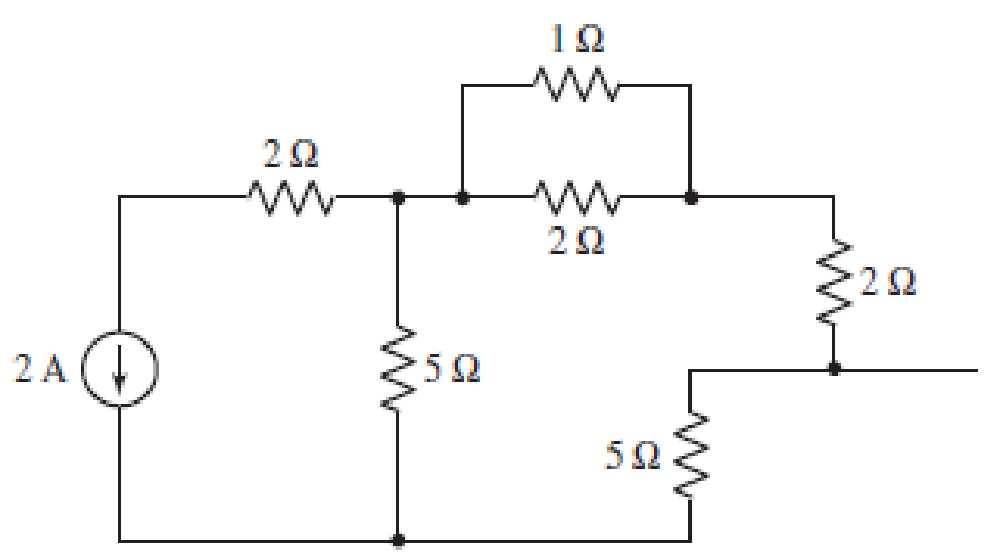
■ FIGURE 3.99
(a)
Find the number of nodes, number of loops and number of branches in the circuit.
Answer to Problem 63E
Number of nodes in the circuit is
Explanation of Solution
The circuit diagram is redrawn as shown in Figure 1.
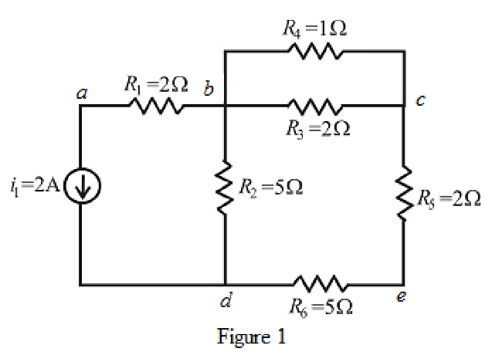
Refer to the redrawn Figure 1.
A point where two or more branches have common connection is known as node.
In Figure 1 two branches are connected at point
Each electrical element or device present in the circuit is known as branch.
There is
The circuit diagram is redrawn as shown in Figure 2,
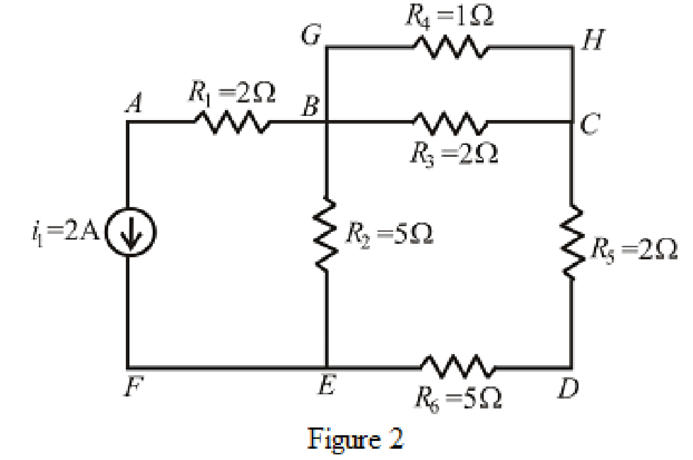
Refer to the redrawn Figure 2,
If starting and ending node is same for a path then it is known as closed path or loop.
Conclusion:
Thus, the number of nodes in the circuit is
(b)
Find the value of current through each resistor.
Answer to Problem 63E
The value of current through
Explanation of Solution
Formula used:
The expression for parallel combination of resistance is as follows.
Here,
Calculation:
The circuit diagram is redrawn as shown in Figure 3.
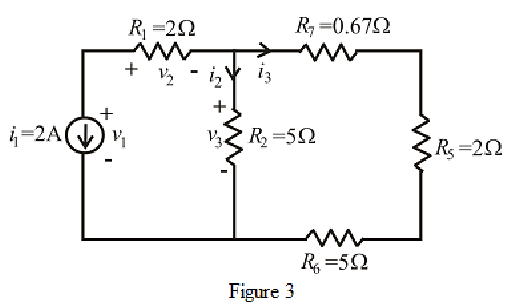
Refer to the redrawn Figure 3.
The expression for current
Here,
The expression for current
Here,
Refer to the redrawn Figure 1.
The expression for current
Here,
The expression for current
Here,
Refer to the redrawn Figure 1.
As
Rearrange for
Refer to the redrawn Figure 3.
As current source direction is downward means change sign of current means value of current is
Substitute
As resistor
So value of current through resistor
Substitute
So, the value of current through resistor
Refer to the redrawn Figure 1.
Substitute
So, the value of current through resistor
Substitute
So, the value of current through resistor
As resistor
Conclusion:
Thus, the value of current through
(c)
Find value of voltage across current source.
Answer to Problem 63E
The voltage across current source is
Explanation of Solution
Formula used:
The expression for voltage is as follows.
Here,
Calculation:
Refer to the redrawn Figure 3.
The expression for voltage
Here,
Refer to the redrawn Figure 3.
Substitute
So value of voltage
Substitute
So value of voltage
Substitute
Conclusion:
Thus, the voltage across current source is
Want to see more full solutions like this?
Chapter 3 Solutions
Loose Leaf for Engineering Circuit Analysis Format: Loose-leaf


- 5-9 A 230 V shunt motor has a nominal arma- ture current of 60 A. If the armature resist- ance is 0.152, calculate the following: a. The counter-emf [V] b. The power supplied to the armature [W] c. The mechanical power developed by the motor, [kW] and [hp] 5-10 a. In Problem 5-9 calculate the initial start- ing current if the motor is directly con- nected across the 230 V line. b. Calculate the value of the starting resistor needed to limit the initial current to 115 A.arrow_forwardhow to solve this?arrow_forwardFor the circuit in Fig. P8.52, choose the load impedance ZLso that the power dissipated in it is a maximum. How much powerwill that be?arrow_forward
- how to solve the attached question? please explain or give reference where required in the solution.arrow_forwardHANDWRITTEN SOLUTION REQUIRED NOT USING CHATGPTarrow_forwardPlease only do part E and F. Please show your work and be as detailed as possible. Please explain the relationship between K the gain and stability of the system. Also, show how to plot the poles and why they are on either the real or imaginary axis. What is it about the example that indicated that? thank youarrow_forward
- Please draw the block diagram for this problem and explain how. thank youarrow_forwardPlease show your work and be as detailed as possible. I would like to really understand the connection between the type of loop, the dampness, and the gain, K. Thank youarrow_forwardIn the zone refining of silicon, an RF-heater is used to remove trace amounts of impuritiesfrom the silicon. If the silicon has the impurity of 10^14 Co (k = 8*10^-6) what is the purityof the crystal after one pass of the zone refiner? After two passes? Plot concentration as afunction of crystal length from 0 to 8ft (total length of the crystal). The width of the moltenzone is 5”.arrow_forward
 Introductory Circuit Analysis (13th Edition)Electrical EngineeringISBN:9780133923605Author:Robert L. BoylestadPublisher:PEARSON
 Delmar's Standard Textbook Of ElectricityElectrical EngineeringISBN:9781337900348Author:Stephen L. HermanPublisher:Cengage Learning
 Programmable Logic ControllersElectrical EngineeringISBN:9780073373843Author:Frank D. PetruzellaPublisher:McGraw-Hill Education
 Fundamentals of Electric CircuitsElectrical EngineeringISBN:9780078028229Author:Charles K Alexander, Matthew SadikuPublisher:McGraw-Hill Education
 Electric Circuits. (11th Edition)Electrical EngineeringISBN:9780134746968Author:James W. Nilsson, Susan RiedelPublisher:PEARSON
 Engineering ElectromagneticsElectrical EngineeringISBN:9780078028151Author:Hayt, William H. (william Hart), Jr, BUCK, John A.Publisher:Mcgraw-hill Education,