
Concept explainers
Videos
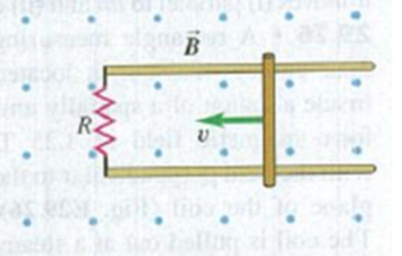
A 0.360-m-long metal bar is pulled to the left by an applied force F. The bar rides on parallel metal rails connected through a 45.0-Ω resistor, as shown in Fig. E29.31, so the apparatus makes a complete circuit. You can ignore the resistance of the bar and rails. The circuit is in a uniform 0.650-T magnetic field that is directed out of the plane of the figure. At the instant when the bar is moving to the left at 5.90 m/s, (a) is the induced current in the circuit clockwise or counterclockwise and (b) what is the rate at which the applied force is doing work on the bar?
Figure E29.31

Learn your wayIncludes step-by-step video

Chapter 29 Solutions
University Physics with Modern Physics (14th Edition)
Additional Science Textbook Solutions
The Cosmic Perspective Fundamentals (2nd Edition)
Physics for Scientists and Engineers with Modern Physics
Physics: Principles with Applications
Life in the Universe (4th Edition)
Physics (5th Edition)
College Physics (10th Edition)


- Consider the system pictured in Figure P28.26. A 15.0-cm horizontal wire of mass 15.0 g is placed between two thin, vertical conductors, and a uniform magnetic field acts perpendicular to the page. The wire is free to move vertically without friction on the two vertical conductors. When a 5.00-A current is directed as shown in the figure, the horizontal wire moves upward at constant velocity in the presence of gravity. (a) What forces act on the horizontal wire, and (b) under what condition is the wire able to move upward at constant velocity? (c) Find the magnitude and direction of the minimum magnetic Field required to move the wire at constant speed. (d) What happens if the magnetic field exceeds this minimum value? Figure P28.26arrow_forwardA square loop whose sides are 6.0-cm long is made with copper wire of radius 1.0 mm. If a magnetic field perpendicular to the loop is changing at a rate of 5.0 mT/s, what is the current in the loop?arrow_forwardA piece of insulated wire is shaped into a figure eight as shown in Figure P23.12. For simplicity, model the two halves of the figure eight as circles. The radius of the upper circle is 5.00 cm and that of the lower circle is 9.00 cm. The wire has a uniform resistance per unit length of 3.00 Ω/m. A uniform magnetic field is applied perpendicular to the plane of the two circles, in the direction shown. The magnetic field is increasing at a constant rate of 2.00 T/s. Find (a) the magnitude and (b) the direction of the induced current in the wire. Figure P23.12arrow_forward
- Review. In studies of the possibility of migrating birds using the Earths magnetic field for navigation, birds have been fitted with coils as caps and collars as shown in Figure P22.39. (a) If the identical coils have radii of 1.20 cm and are 2.20 cm apart, with 50 turns of wire apiece, what current should they both carry to produce a magnetic field of 4.50 105 T halfway between them? (b) If the resistance of each coil is 210 V, what voltage should the battery supplying each coil have? (c) What power is delivered to each coil? Figure P22.39arrow_forwardA circular loop of wire with a radius of 4.0 cm is in a uniform magnetic field of magnitude 0.060 T. The plane of the loop is perpendicular to the direction of the magnetic field. In a time interval of 0.50 s, the magnetic field changes to the opposite direction with a magnitude of 0.040 T. What is the magnitude of the average emf induced in the loop? (a) 0.20 V (b) 0.025 V (c) 5.0 mV (d) 1.0 mV (e) 0.20 mVarrow_forwardA constant magnetic field of 0.275 T points through a circular loop of wire with radius 3.50 cm as shown in Figure P32.1. a. What is the magnetic flux through the loop? b. Is a current induced in the loop? Explain. FIGURE P32.1arrow_forward
- A toroid has a major radius R and a minor radius r and is tightly wound with N turns of wire on a hollow cardboard torus. Figure P31.6 shows half of this toroid, allowing us to see its cross section. If R r, the magnetic field in the region enclosed by the wire is essentially the same as the magnetic field of a solenoid that has been bent into a large circle of radius R. Modeling the field as the uniform field of a long solenoid, show that the inductance of such a toroid is approximately L=120N2r2R Figure P31.6arrow_forwardA wire is bent in the form of a square loop with sides of length L (Fig. P30.24). If a steady current I flows in the loop, determine the magnitude of the magnetic field at point P in the center of the square. FIGURE P30.24arrow_forwardA circular coil 15.0 cm in radius and composed of 145 tightly wound turns carries a current of 2.50 A in the counterclockwise direction, where the plane of the coil makes an angle of 15.0 with the y axis (Fig. P30.73). The coil is free to rotate about the z axis and is placed in a region with a uniform magnetic field given by B=1.35jT. a. What is the magnitude of the magnetic torque on the coil? b. In what direction will the coil rotate? FIGURE P30.73arrow_forward
- Figure P23.15 shows a top view of a bar that can slide on two frictionless rails. The resistor is R = 6.00 , and a 2.50-T magnetic field is directed perpendicularly downward, into the paper. Let = 1.20 m. (a) Calculate the applied force required to move the bar to the right at a constant speed of 2.00 m/s. (b) At what rate is energy delivered to the resistor? Figure P23.15 Problems 15 through 18.arrow_forwardUnreasonable results Frustrated by the small Hall voltage obtained in blood flow measurements, a medical physicist decides to increase the applied magnetic field strength to get a 0.500-V output for blood moving at 30.0 cm/s in a 1.50-cm-diameter vessel. (a) What magnetic field strength is needed? (b) What is unreasonable about this result? (C) Which premise is responsible?arrow_forwardA rectangular coil consists of N = 100 closely wrapped turns and has dimensions a = 0.400 m and b = 0.300 m. The coil is hinged along the y axis, and its plane makes an angle = 30.0 with the x axis (Fig. P22.25). (a) What is the magnitude of the torque exerted on the coil by a uniform magnetic field B = 0.800 T directed in the positive x direction when the current is I = 1.20 A in the direction shown? (b) What is the expected direction of rotation of the coil? Figure P22.25arrow_forward
 Physics for Scientists and Engineers: Foundations...PhysicsISBN:9781133939146Author:Katz, Debora M.Publisher:Cengage Learning
 Principles of Physics: A Calculus-Based TextPhysicsISBN:9781133104261Author:Raymond A. Serway, John W. JewettPublisher:Cengage Learning
 Physics for Scientists and EngineersPhysicsISBN:9781337553278Author:Raymond A. Serway, John W. JewettPublisher:Cengage Learning
 Physics for Scientists and Engineers with Modern ...PhysicsISBN:9781337553292Author:Raymond A. Serway, John W. JewettPublisher:Cengage Learning
 College PhysicsPhysicsISBN:9781305952300Author:Raymond A. Serway, Chris VuillePublisher:Cengage Learning
 College PhysicsPhysicsISBN:9781285737027Author:Raymond A. Serway, Chris VuillePublisher:Cengage Learning