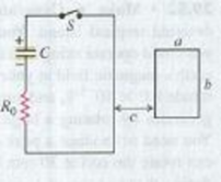
CP CALC In the circuit shown in Fig. P29.47, the capacitor has capacitance C = 20μF and is initially charged to 100 V with the polarity shown. The resistor R0 has resistance 10 Ω. At time t = 0 the switch S is closed. The small circuit is not connected in any way to the large one. The wire of the small circuit has a resistance of 1.0 Ω/m and contains 25 loops. The large circuit is a rectangle 2.0 m by 4.0 m, while the small one has dimensions a = 10.0 cm and b = 20.0 cm. The distance c is 5.0 cm. (The figure is not drawn to scale.) Both circuits are held stationary. Assume that only the wire nearest the small circuit produces an appreciable magnetic field through it. (a) Find the current in the large circuit 200 μs after S is closed. (b) Find the current in the small circuit 200 μs after S is closed. (Hint: See Exercise 29.7.) (c) Find the direction of the current in the small circuit. (d) Justify why we can ignore the magnetic field from all the wires of the large circuit except for the wire closest to the small circuit.
Figure P29.47

Want to see the full answer?
Check out a sample textbook solution
Chapter 29 Solutions
University Physics with Modern Physics (14th Edition)
Additional Science Textbook Solutions
Campbell Biology in Focus (2nd Edition)
Genetic Analysis: An Integrated Approach (3rd Edition)
Anatomy & Physiology (6th Edition)
Concepts of Genetics (12th Edition)
Microbiology: An Introduction
Campbell Essential Biology with Physiology (5th Edition)
- The de-excitation of a state occurs by competing emission and relaxation processes. If the relaxation mechanisms are very effective:a) the emission of radiation is largeb) the emission of radiation is smallc) the emission occurs at a shorter wavelengthd) the de-excitation occurs only by emission processesarrow_forwardm C A block of mass m slides down a ramp of height hand collides with an identical block that is initially at rest. The two blocks stick together and travel around a loop of radius R without losing contact with the track. Point A is at the top of the loop, point B is at the end of a horizon- tal diameter, and point C is at the bottom of the loop, as shown in the figure above. Assume that friction between the track and blocks is negligible. (a) The dots below represent the two connected blocks at points A, B, and C. Draw free-body dia- grams showing and labeling the forces (not com ponents) exerted on the blocks at each position. Draw the relative lengths of all vectors to reflect the relative magnitude of the forces. Point A Point B Point C (b) For each of the following, derive an expression in terms of m, h, R, and fundamental constants. i. The speed of moving block at the bottom of the ramp, just before it contacts the stationary block ii. The speed of the two blocks immediately…arrow_forwardThe velocity of an elevator is given by the graph shown. Assume the positive direction is upward. Velocity (m/s) 3.0 2.5 2.0 1.5 1.0 0.5 0 0 5.0 10 15 20 25 Time (s) (a) Briefly describe the motion of the elevator. Justify your description with reference to the graph. (b) Assume the elevator starts from an initial position of y = 0 at t=0. Deriving any numerical values you need from the graph: i. Write an equation for the position as a function of time for the elevator from t=0 to t = 3.0 seconds. ii. Write an equation for the position as a function of time for the elevator from t = 3.0 seconds to t = 19 seconds. (c) A student of weight mg gets on the elevator and rides the elevator during the time interval shown in the graph. Consider the force of con- tact, F, between the floor and the student. How Justify your answer with reference to the graph does F compare to mg at the following times? and your equations above. i. = 1.0 s ii. = 10.0 sarrow_forward
- Students are asked to use circular motion to measure the coefficient of static friction between two materials. They have a round turntable with a surface made from one of the materials, for which they can vary the speed of rotation. They also have a small block of mass m made from the sec- ond material. A rough sketch of the apparatus is shown in the figure below. Additionally they have equipment normally found in a physics classroom. Axis m (a) Briefly describe a procedure that would allow you to use this apparatus to calculate the coefficient of static friction, u. (b) Based on your procedure, determine how to analyze the data collected to calculate the coefficient of friction. (c) One group of students collects the following data. r (m) fm (rev/s) 0.050 1.30 0.10 0.88 0.15 0.74 0.20 0.61 0.25 0.58 i. Use the empty spaces in the table as needed to calculate quantities that would allow you to use the slope of a line graph to calculate the coefficient of friction, providing labels with…arrow_forwardPART Aarrow_forwardanswer both questionarrow_forward
- Only part A.) of the questionarrow_forwardIn general it is best to conceptualize vectors as arrows in space, and then to make calculations with them using their components. (You must first specify a coordinate system in order to find the components of each arrow.) This problem gives you some practice with the components. Let vectors A = (1,0, -3), B = (-2, 5, 1), and C = (3,1,1). Calculate the following, and express your answers as ordered triplets of values separated by commas.arrow_forwardIn general it is best to conceptualize vectors as arrows in space, and then to make calculations with them using their components. (You must first specify a coordinate system in order to find the components of each arrow.) This problem gives you some practice with the components. Let vectors A = (1,0, −3), B = (-2, 5, 1), and C = (3,1,1). Calculate the following, and express your answers as ordered triplets of values separated by commas.arrow_forward
 Physics for Scientists and Engineers: Foundations...PhysicsISBN:9781133939146Author:Katz, Debora M.Publisher:Cengage Learning
 Physics for Scientists and Engineers with Modern ...PhysicsISBN:9781337553292Author:Raymond A. Serway, John W. JewettPublisher:Cengage Learning
 Physics for Scientists and EngineersPhysicsISBN:9781337553278Author:Raymond A. Serway, John W. JewettPublisher:Cengage Learning
 Principles of Physics: A Calculus-Based TextPhysicsISBN:9781133104261Author:Raymond A. Serway, John W. JewettPublisher:Cengage Learning
 Physics for Scientists and Engineers, Technology ...PhysicsISBN:9781305116399Author:Raymond A. Serway, John W. JewettPublisher:Cengage Learning
 College PhysicsPhysicsISBN:9781305952300Author:Raymond A. Serway, Chris VuillePublisher:Cengage Learning


