In Fig. P29.51 the loop is being pulled lo the right at constant speed ʋ . A constant current I flows in the long wire, in the direction shown. (a) Calculate the magnitude of the net emf ε induced in the loop. Do this two ways: (i) by using Faraday’s law of induction ( Hint: See Exercise 29.7) and (ii) by looking at the emf induced in each segment of the loop due to its motion. (b) Find the direction (clockwise or counterclockwise) of the current induced in the loop. Do this two ways: (i) using Lenz’s law and (ii) using the magnetic force on charges in the loop. (c) Check your answer for the emf in part (a) in the following special cases to see whether it is physically reasonable: (i) The loop is stationary; (ii) the loop is very thin, so a → 0; (iii) the loop gets very far from the wire. Figure P29.51
In Fig. P29.51 the loop is being pulled lo the right at constant speed ʋ . A constant current I flows in the long wire, in the direction shown. (a) Calculate the magnitude of the net emf ε induced in the loop. Do this two ways: (i) by using Faraday’s law of induction ( Hint: See Exercise 29.7) and (ii) by looking at the emf induced in each segment of the loop due to its motion. (b) Find the direction (clockwise or counterclockwise) of the current induced in the loop. Do this two ways: (i) using Lenz’s law and (ii) using the magnetic force on charges in the loop. (c) Check your answer for the emf in part (a) in the following special cases to see whether it is physically reasonable: (i) The loop is stationary; (ii) the loop is very thin, so a → 0; (iii) the loop gets very far from the wire. Figure P29.51
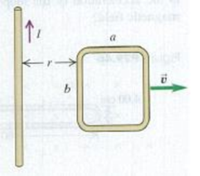
In Fig. P29.51 the loop is being pulled lo the right at constant speed ʋ. A constant current I flows in the long wire, in the direction shown. (a) Calculate the magnitude of the net emf ε induced in the loop. Do this two ways: (i) by using Faraday’s law of induction (Hint: See Exercise 29.7) and (ii) by looking at the emf induced in each segment of the loop due to its motion. (b) Find the direction (clockwise or counterclockwise) of the current induced in the loop. Do this two ways: (i) using Lenz’s law and (ii) using the magnetic force on charges in the loop. (c) Check your answer for the emf in part (a) in the following special cases to see whether it is physically reasonable: (i) The loop is stationary; (ii) the loop is very thin, so a → 0; (iii) the loop gets very far from the wire.
The figure gives the acceleration a versus time t for a particle moving along an x axis. The a-axis scale is set by as = 12.0 m/s². At t = -2.0
s, the particle's velocity is 11.0 m/s. What is its velocity at t = 6.0 s?
a (m/s²)
as
-2
0
2
t(s)
4
Two solid cylindrical rods AB and BC are welded together at B and loaded as shown. Knowing that the average normal stress must not
exceed 150 MPa in either rod, determine the smallest allowable values of the diameters d₁ and d2. Take P= 85 kN.
P
125 kN
B
125 kN
C
0.9 m
1.2 m
The smallest allowable value of the diameter d₁ is
The smallest allowable value of the diameter d₂ is
mm.
mm.
Westros, from Game of Thrones, has an area of approximately 6.73⋅106 miles26.73⋅106miles2. Convert the area of Westros to km2 where 1.00 mile = 1.609 km.
Chapter 29 Solutions
University Physics with Modern Physics (14th Edition)
College Physics: A Strategic Approach (3rd Edition)
Knowledge Booster
Learn more about
Need a deep-dive on the concept behind this application? Look no further. Learn more about this topic, physics and related others by exploring similar questions and additional content below.
What is Electromagnetic Induction? | Faraday's Laws and Lenz Law | iKen | iKen Edu | iKen App; Author: Iken Edu;https://www.youtube.com/watch?v=3HyORmBip-w;License: Standard YouTube License, CC-BY


 Physics for Scientists and Engineers, Technology ...PhysicsISBN:9781305116399Author:Raymond A. Serway, John W. JewettPublisher:Cengage Learning
 Physics for Scientists and Engineers: Foundations...PhysicsISBN:9781133939146Author:Katz, Debora M.Publisher:Cengage Learning
 Principles of Physics: A Calculus-Based TextPhysicsISBN:9781133104261Author:Raymond A. Serway, John W. JewettPublisher:Cengage Learning
 Physics for Scientists and EngineersPhysicsISBN:9781337553278Author:Raymond A. Serway, John W. JewettPublisher:Cengage Learning
 Physics for Scientists and Engineers with Modern ...PhysicsISBN:9781337553292Author:Raymond A. Serway, John W. JewettPublisher:Cengage Learning