
Concept explainers
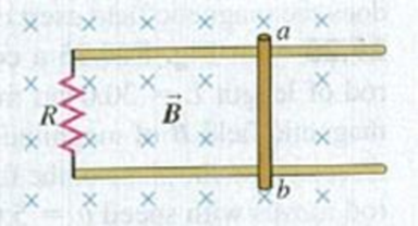
A 0.650-m-long metal bar is pulled to the right at a steady 5.0 m/s perpendicular to a uniform. 0.750-T magnetic field. The bar rides on parallel metal rails connected through a 25.0-Ω resistor (Fig. E29.30). so the apparatus makes a complete circuit. Ignore the resistance of the bar and the rails. (a) Calculate the magnitude of the emf induced in the circuit. (b) Find the direction of the current induced in the circuit by using (i) the magnetic force on the charges in the moving bar; (ii) Faraday’s law; (iii) Lenz’s law. (c) Calculate the current through the resistor.
Figure E29.30

Learn your wayIncludes step-by-step video

Chapter 29 Solutions
University Physics with Modern Physics (14th Edition)
Additional Science Textbook Solutions
Chemistry: Structure and Properties (2nd Edition)
Anatomy & Physiology (6th Edition)
Microbiology with Diseases by Body System (5th Edition)
College Physics: A Strategic Approach (3rd Edition)
Chemistry: An Introduction to General, Organic, and Biological Chemistry (13th Edition)
Genetic Analysis: An Integrated Approach (3rd Edition)


- A bungee jumper plans to bungee jump from a bridge 64.0 m above the ground. He plans to use a uniform elastic cord, tied to a harness around his body, to stop his fall at a point 6.00 m above the water. Model his body as a particle and the cord as having negligible mass and obeying Hooke's law. In a preliminary test he finds that when hanging at rest from a 5.00 m length of the cord, his body weight stretches it by 1.55 m. He will drop from rest at the point where the top end of a longer section of the cord is attached to the bridge. (a) What length of cord should he use? Use subscripts 1 and 2 respectively to represent the 5.00 m test length and the actual jump length. Use Hooke's law F = KAL and the fact that the change in length AL for a given force is proportional the length L (AL = CL), to determine the force constant for the test case and for the jump case. Use conservation of mechanical energy to determine the length of the rope. m (b) What maximum acceleration will he…arrow_forward9 V 300 Ω www 100 Ω 200 Ω www 400 Ω 500 Ω www 600 Ω ww 700 Ω Figure 1: Circuit symbols for a variety of useful circuit elements Problem 04.07 (17 points). Answer the following questions related to the figure below. A What is the equivalent resistance of the network of resistors in the circuit below? B If the battery has an EMF of 9V and is considered as an ideal batter (internal resistance is zero), how much current flows through it in this circuit? C If the 9V EMF battery has an internal resistance of 2 2, would this current be larger or smaller? By how much? D In the ideal battery case, calculate the current through and the voltage across each resistor in the circuit.arrow_forwardhelparrow_forward
- If the block does reach point B, how far up the curved portion of the track does it reach, and if it does not, how far short of point B does the block come to a stop? (Enter your answer in m.)arrow_forwardTruck suspensions often have "helper springs" that engage at high loads. One such arrangement is a leaf spring with a helper coil spring mounted on the axle, as shown in the figure below. When the main leaf spring is compressed by distance yo, the helper spring engages and then helps to support any additional load. Suppose the leaf spring constant is 5.05 × 10⁵ N/m, the helper spring constant is 3.50 × 10⁵ N/m, and y = 0.500 m. Truck body yo Main leaf spring -"Helper" spring Axle (a) What is the compression of the leaf spring for a load of 6.00 × 10⁵ N? Your response differs from the correct answer by more than 10%. Double check your calculations. m (b) How much work is done in compressing the springs? ☑ Your response differs significantly from the correct answer. Rework your solution from the beginning and check each step carefully. Jarrow_forwardA spring is attached to an inclined plane as shown in the figure. A block of mass m = 2.71 kg is placed on the incline at a distance d = 0.285 m along the incline from the end of the spring. The block is given a quick shove and moves down the incline with an initial speed v = 0.750 m/s. The incline angle is = 20.0°, the spring constant is k = 505 N/m, and we can assume the surface is frictionless. By what distance (in m) is the spring compressed when the block momentarily comes to rest? m m 0 k wwwwarrow_forward
- A block of mass m = 2.50 kg situated on an incline at an angle of k=100 N/m www 50.0° is connected to a spring of negligible mass having a spring constant of 100 N/m (Fig. P8.54). The pulley and incline are frictionless. The block is released from rest with the spring initially unstretched. Ө m i (a) How far does it move down the frictionless incline before coming to rest? m (b) What is its acceleration at its lowest point? Magnitude m/s² Direction O up the incline down the inclinearrow_forward(a) A 15.0 kg block is released from rest at point A in the figure below. The track is frictionless except for the portion between points B and C, which has a length of 6.00 m. The block travels down the track, hits a spring of force constant 2,100 N/m, and compresses the spring 0.250 m from its equilibrium position before coming to rest momentarily. Determine the coefficient of kinetic friction between the block and the rough surface between points B and C. -A 3.00 m B C -6.00 m i (b) What If? The spring now expands, forcing the block back to the left. Does the block reach point B? Yes No If the block does reach point B, how far up the curved portion of the track does it reach, and if it does not, how far short of point B does the block come to a stop? (Enter your answer in m.) marrow_forwardA ball of mass m = 1.95 kg is released from rest at a height h = 57.0 cm above a light vertical spring of force constant k as in Figure [a] shown below. The ball strikes the top of the spring and compresses it a distance d = 7.80 cm as in Figure [b] shown below. Neglecting any energy losses during the collision, find the following. т m a d T m b i (a) Find the speed of the ball just as it touches the spring. 3.34 m/s (b) Find the force constant of the spring. Your response differs from the correct answer by more than 10%. Double check your calculations. kN/marrow_forward
- I need help with questions 1-10 on my solubility curve practice sheet. I tried to my best ability on the answers, however, i believe they are wrong and I would like to know which ones a wrong and just need help figuring it out.arrow_forwardQuestion: For a liquid with typical values a = 10-3K-¹ K = 10-4 bar-1 V=50 cm³ mol-1, Cp 200 J mol-1K-1, calculate the following quantities at 300 K and 1 bar for one mole of gas: 1. () P ән 2. (9) T 3. (V) T 4. (1) P 5. (9) T 6. Cv 7. (OF)Tarrow_forwardA,B,C AND Darrow_forward
 Glencoe Physics: Principles and Problems, Student...PhysicsISBN:9780078807213Author:Paul W. ZitzewitzPublisher:Glencoe/McGraw-Hill
 Principles of Physics: A Calculus-Based TextPhysicsISBN:9781133104261Author:Raymond A. Serway, John W. JewettPublisher:Cengage Learning
 Physics for Scientists and Engineers with Modern ...PhysicsISBN:9781337553292Author:Raymond A. Serway, John W. JewettPublisher:Cengage Learning
 College PhysicsPhysicsISBN:9781305952300Author:Raymond A. Serway, Chris VuillePublisher:Cengage Learning
 Physics for Scientists and Engineers, Technology ...PhysicsISBN:9781305116399Author:Raymond A. Serway, John W. JewettPublisher:Cengage Learning
 College PhysicsPhysicsISBN:9781285737027Author:Raymond A. Serway, Chris VuillePublisher:Cengage Learning