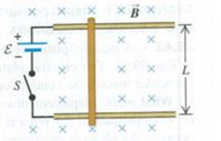
CP CALC Terminal Speed. A bar of length L = 0.36 m is free to slide without friction on horizontal rails as shown in Fig. P29.56. A uniform magnetic field B = 2.4 T is directed into the plane of the figure. At one end of the rails there is a battery with emf ε = 12 V and a switch S. The bar has mass 0.90 kg and resistance 5.0 Ω; ignore all other resistance in the circuit. The switch is closed at time t = 0. (a) Sketch the bar’s speed as a function of time. (b) Just after the switch is closed, what is the acceleration of the bar? (c) What is the acceleration of the bar when its speed is 2.0 m/s? (d) What is the bar’s terminal speed?
Figure P29.56

Want to see the full answer?
Check out a sample textbook solution
Chapter 29 Solutions
University Physics with Modern Physics (14th Edition)
Additional Science Textbook Solutions
Applications and Investigations in Earth Science (9th Edition)
Campbell Essential Biology with Physiology (5th Edition)
Cosmic Perspective Fundamentals
Genetic Analysis: An Integrated Approach (3rd Edition)
Campbell Biology: Concepts & Connections (9th Edition)
College Physics: A Strategic Approach (3rd Edition)
- 3.37(a) Five free electrons exist in a three-dimensional infinite potential well with all three widths equal to \( a = 12 \, \text{Å} \). Determine the Fermi energy level at \( T = 0 \, \text{K} \). (b) Repeat part (a) for 13 electrons. Book: Semiconductor Physics and Devices 4th ed, NeamanChapter-3Please expert answer only. don't give gpt-generated answers, & please clear the concept of quantum states for determining nx, ny, nz to determine E, as I don't have much idea about that topic.arrow_forwardNo chatgpt pls will upvotearrow_forwardUse the following information to answer the next question. Two mirrors meet an angle, a, of 105°. A ray of light is incident upon mirror A at an angle, i, of 42°. The ray of light reflects off mirror B and then enters water, as shown below: Incident ray at A Note: This diagram is not to scale. a Air (n = 1.00) Water (n = 1.34) 1) Determine the angle of refraction of the ray of light in the water. Barrow_forward
- Hi can u please solvearrow_forward6. Bending a lens in OpticStudio or OSLO. In either package, create a BK7 singlet lens of 10 mm semi-diameter and with 10 mm thickness. Set the wavelength to the (default) 0.55 microns and a single on-axis field point at infinite object distance. Set the image distance to 200 mm. Make the first surface the stop insure that the lens is fully filled (that is, that the entrance beam has a radius of 10 mm). Use the lens-maker's equation to calculate initial glass curvatures assuming you want a symmetric, bi-convex lens with an effective focal length of 200 mm. Get this working and examine the RMS spot size using the "Text" tab of the Spot Diagram analysis tab (OpticStudio) or the Spd command of the text widnow (OSLO). You should find the lens is far from diffraction limited, with a spot size of more than 100 microns. Now let's optimize this lens. In OpticStudio, create a default merit function optimizing on spot size.Then insert one extra line at the top of the merit function. Assign the…arrow_forwardNo chatgpt pls will upvote Already got wrong chatgpt answer .arrow_forward
- Use the following information to answer the next question. Two mirrors meet an angle, a, of 105°. A ray of light is incident upon mirror A at an angle, i, of 42°. The ray of light reflects off mirror B and then enters water, as shown below: A Incident ray at A Note: This diagram is not to scale. Air (n = 1.00) Water (n = 1.34) Barrow_forwardUse the following information to answer the next question. Two mirrors meet an angle, a, of 105°. A ray of light is incident upon mirror A at an angle, i, of 42°. The ray of light reflects off mirror B and then enters water, as shown below: A Incident ray at A Note: This diagram is not to scale. Air (n = 1.00) Water (n = 1.34) Barrow_forwardGood explanation it sure experts solve it.arrow_forward
- No chatgpt pls will upvote Asaparrow_forwardA satellite has a mass of 100kg and is located at 2.00 x 10^6 m above the surface of the earth. a) What is the potential energy associated with the satellite at this loction? b) What is the magnitude of the gravitational force on the satellite?arrow_forwardNo chatgpt pls will upvotearrow_forward
 Glencoe Physics: Principles and Problems, Student...PhysicsISBN:9780078807213Author:Paul W. ZitzewitzPublisher:Glencoe/McGraw-Hill
 Principles of Physics: A Calculus-Based TextPhysicsISBN:9781133104261Author:Raymond A. Serway, John W. JewettPublisher:Cengage Learning
 Physics for Scientists and EngineersPhysicsISBN:9781337553278Author:Raymond A. Serway, John W. JewettPublisher:Cengage Learning
 Physics for Scientists and Engineers with Modern ...PhysicsISBN:9781337553292Author:Raymond A. Serway, John W. JewettPublisher:Cengage Learning
 Physics for Scientists and Engineers, Technology ...PhysicsISBN:9781305116399Author:Raymond A. Serway, John W. JewettPublisher:Cengage Learning
 Physics for Scientists and Engineers: Foundations...PhysicsISBN:9781133939146Author:Katz, Debora M.Publisher:Cengage Learning


