
Electric Motor Control
10th Edition
ISBN: 9781305177611
Author: Herman
Publisher: Cengage
expand_more
expand_more
format_list_bulleted
Concept explainers
Videos
Textbook Question
Chapter 21, Problem 8SQ
What is the sequence of the operations if the limit switches, shown in Figure 21–6, are used. (Limit switches were covered in Unit 13.)
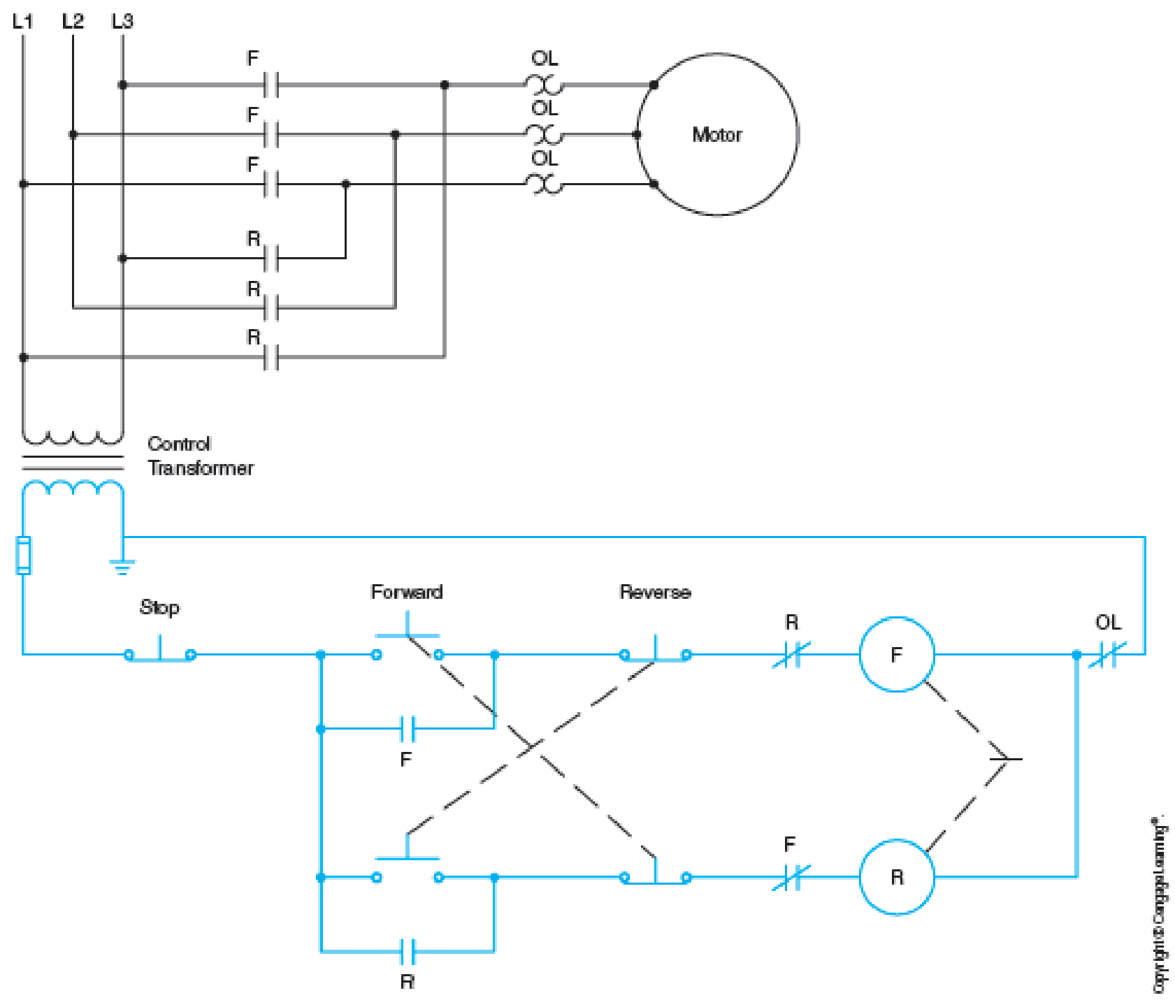
Fig. 21–6 Elementary diagram of the reversing starter shown in Figure 21–1. The
Expert Solution & Answer

Trending nowThis is a popular solution!

Students have asked these similar questions
Can you solve for the voltage across 1kohm resistor when both voltage sources are on. Additionally can you solve for when 2V is shorted and 5V is on. Then, when 2V is on and 5V is shorted
a. A silicon sample maintained at room temperature is uniformly doped with ND=10¹6/cm³
donors. Calculate the resistivity of the sample.
b. The silicon sample of part (a) is "compensated" by adding NA=1016/cm³ acceptors. Calculate
the resistivity of the compensated sample.
c. Compute the resistivity of intrinsic silicon at room temperature.
d. A 500 resistor is to be made from a bar-shaped piece of n-type Si. The bar has a cross
sectional area of 102 cm² and a current-carrying length of 1 cm. Determine the doping
required.
μn or μp (cm²/V-sec)
1000
Electrons
Holes
NA or ND (cm³)
1x10¹⁴
Мет
Mp
(cm2V-sec)
1358
461
2
1357 460
100
5
1352
459
1 x 10¹⁵
1345
458
2
1332
455
5
1298
448
1 x 10¹⁶....
1248 437
2
1165 419
5
986 378
1 x 10¹⁷
801
331
10
1014
1015
1016
NA or ND (cm-³)
1017
1018
Silicon
T = 300 K
4. Two different silicon samples maintained at 300K are characterized by the energy band diagrams.
Answer the questions that follow after choosing a specific diagram for analysis.
a) Do equilibrium conditions prebail? How do you know?
b) Sketch the electrostatic potential (V) inside the semiconductor as a function of x.
c) Sketch the electric field (ε) inside the semiconductor as a function of x.
EF
Ec
E₁
Ev
E₁
EF
Ev
X
X
0
L/2
L
0
L/2
L
3.
Chapter 21 Solutions
Electric Motor Control
Ch. 21 - How is a change in the direction of rotation of a...Ch. 21 - Prob. 2SQCh. 21 - If a reversing control circuit contains...Ch. 21 - How is auxiliary contact interlocking achieved on...Ch. 21 - After the forward coil has been energized, is the...Ch. 21 - If a mechanical interlock is the only means of...Ch. 21 - If pilot lights are to indicate which coil is...Ch. 21 - What is the sequence of the operations if the...Ch. 21 - In place of the push buttons in Figure 214, draw a...Ch. 21 - From the elementary drawing in Figure 2110,...
Knowledge Booster


Learn more about
Need a deep-dive on the concept behind this application? Look no further. Learn more about this topic, electrical-engineering and related others by exploring similar questions and additional content below.Similar questions
- See BOTH images to answer correctly thxarrow_forwarda. An average hole drift velocity of 103 cm/sec results when 2V is applied across a 1 cm long semiconductor bar. What is the hole mobility inside the bar? b. Name the two dominant carrier scattering mechanisms in nondegeneratedly doped semiconductors of device quality. c. For a give semiconductor the carrier mobilities in intrinsic material are (choose one: higher than, lower than, the same as) those in heavily doped material. Briefly explain why the mobilites in intrinsic material are (chosen answer) those in heavily doped material.arrow_forwardFind the steady-state expression for vo(t) in the following circuit if vg (t) = 64 cos(8000t) V. 31.25 nF HE + Vg + - 2 ΚΩ Vo 500 mHarrow_forward
- Use PSpice to model the differential amplifier circuit shown in Fig. 4 in DIBO mode (double input balanced output). Use 2N3904 BJTs and use appropriate values for resistors (you can choose the values that will not lead to excessive gain and saturation) to demonstrate that the circuit provides differential amplification. Use Vcc = 5 and Vee = 5. Use a pair of sinusoids with opposing polarity (180 degree phase shift) as the inputs to the differential amplifier. Recall from the theory ic is needed to compute re. Make sure that the conditions set in the analysis of DIBO circuit are satisfied. Assume Rs1 = Rs2 50 Ω. Does your simulation match the theoretical gain? Explain any differences.arrow_forwardDerive the expression for the voltage gain of DIBO differential amplifier using AC analysis.arrow_forwardConsider the following circuit. + - 1.2 ΚΩ ig (1) vo ΣΕ ΚΩ € 50 nF 200 mH a) [6 pts] The frequency of the source current in the circuit is adjusted until vo is in phase with ig. What is the value of o in radians per second? (Hint: if vo is in phase with ig, the phase of total impedance must be zero (Ztot = vol ig), which means the phase of total admittance is zero. It will be easy to work with admittance in this question because the components are in parallel.) b) [2 pts] What is the total impedance at the frequency found in (a)? c) [2 pts] Ifig=2.5 cosoot mA (where o is the frequency found in [a]), what is the steady-state expression for vo?arrow_forward
- Consider the following circuit with ig (t) = 200 cos(5000t) mA. 240 ΩΣ + 80 2: 2.5 µF 48 mH a) [3 pts] Obtain and draw the frequency-domain circuit. b) [3 pts] Use the current division to find the current flowing through the 240 2 resistor. c) [3 pts] Then calculate Vo in phasor form. d) [1 pts] Write the steady-state expression for vo(t).arrow_forwardQ-Draw a sample and hold electronic circuit using op-amp then explain its operation. I hope the solution is from a human being and not from intelligencearrow_forwardDesign an AC-coupled (input and output) amplifier with a gain of -8 which has identical 3 dB corner frequencies of 10 kHz for high pass coupling at the input and output. Assume a power supply of 5 volts.arrow_forward
- Find Laplace inverse for -25 -1 e S-1arrow_forwardThis question and its solution. Is the solution correct? If the solution is correct, assume that let R2 = 20 and a=500 . If it is wrong, solve it in your own way, away from the sources, and explain to me in detail with a pen and paper, please.arrow_forwardcan you compute the values inside the blue circles using the data from the plan above them? Please disregard the values (data/numbers) inside the circles.arrow_forward
arrow_back_ios
SEE MORE QUESTIONS
arrow_forward_ios
Recommended textbooks for you
 Electricity for Refrigeration, Heating, and Air C...Mechanical EngineeringISBN:9781337399128Author:Russell E. SmithPublisher:Cengage Learning
 Delmar's Standard Textbook Of ElectricityElectrical EngineeringISBN:9781337900348Author:Stephen L. HermanPublisher:Cengage Learning
Electricity for Refrigeration, Heating, and Air C...
Mechanical Engineering
ISBN:9781337399128
Author:Russell E. Smith
Publisher:Cengage Learning
Delmar's Standard Textbook Of Electricity
Electrical Engineering
ISBN:9781337900348
Author:Stephen L. Herman
Publisher:Cengage Learning
Single Phase Induction Motor, How it works ?; Author: Lesics;https://www.youtube.com/watch?v=awrUxv7B-a8;License: Standard Youtube License