
Electric Motor Control
10th Edition
ISBN: 9781305177611
Author: Herman
Publisher: Cengage
expand_more
expand_more
format_list_bulleted
Concept explainers
Videos
Textbook Question
Chapter 21, Problem 10SQ
In place of the push buttons in Figure 21–4, draw a heavy-duty selector switch for forward-reverse-stop control. Show the target table for this selector switch.
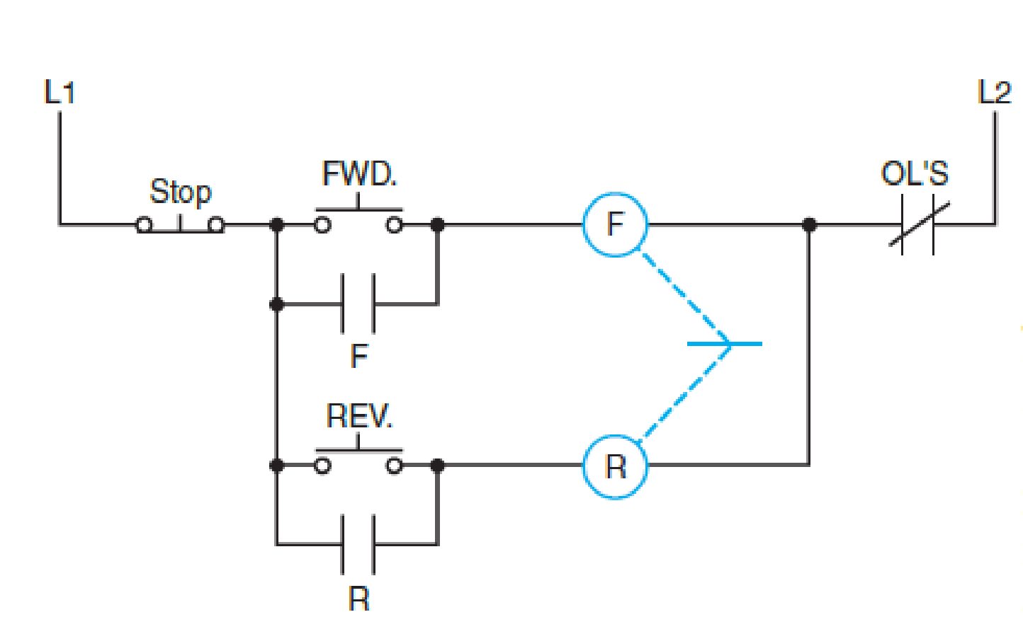
FIG. 21–4
Expert Solution & Answer

Trending nowThis is a popular solution!

Students have asked these similar questions
Use PSpice to model the differential amplifier circuit shown in Fig. 4 in DIBO mode (double input balanced output). Use 2N3904 BJTs and use appropriate values for resistors (you can choose the values that will not lead to excessive gain and saturation) to demonstrate that the circuit provides differential amplification. Use Vcc = 5 and Vee = 5. Use a pair of sinusoids with opposing polarity (180 degree phase shift) as the inputs to the differential amplifier. Recall from the theory ic is needed to compute re. Make sure that the conditions set in the analysis of DIBO circuit are satisfied. Assume Rs1 = Rs2 50 Ω. Does your simulation match the theoretical gain? Explain any differences.
Derive the expression for the voltage gain of DIBO differential amplifier using AC analysis.
Consider the following circuit.
+
- 1.2 ΚΩ
ig (1) vo
ΣΕ ΚΩ
€ 50 nF
200 mH
a) [6 pts] The frequency of the source current in the circuit is adjusted until vo is in phase with ig. What is
the value of o in radians per second? (Hint: if vo is in phase with ig, the phase of total impedance must be
zero (Ztot = vol ig), which means the phase of total admittance is zero. It will be easy to work with
admittance in this question because the components are in parallel.)
b) [2 pts] What is the total impedance at the frequency found in (a)?
c) [2 pts] Ifig=2.5 cosoot mA (where o is the frequency found in [a]), what is the steady-state expression
for vo?
Chapter 21 Solutions
Electric Motor Control
Ch. 21 - How is a change in the direction of rotation of a...Ch. 21 - Prob. 2SQCh. 21 - If a reversing control circuit contains...Ch. 21 - How is auxiliary contact interlocking achieved on...Ch. 21 - After the forward coil has been energized, is the...Ch. 21 - If a mechanical interlock is the only means of...Ch. 21 - If pilot lights are to indicate which coil is...Ch. 21 - What is the sequence of the operations if the...Ch. 21 - In place of the push buttons in Figure 214, draw a...Ch. 21 - From the elementary drawing in Figure 2110,...
Knowledge Booster


Learn more about
Need a deep-dive on the concept behind this application? Look no further. Learn more about this topic, electrical-engineering and related others by exploring similar questions and additional content below.Similar questions
- Consider the following circuit with ig (t) = 200 cos(5000t) mA. 240 ΩΣ + 80 2: 2.5 µF 48 mH a) [3 pts] Obtain and draw the frequency-domain circuit. b) [3 pts] Use the current division to find the current flowing through the 240 2 resistor. c) [3 pts] Then calculate Vo in phasor form. d) [1 pts] Write the steady-state expression for vo(t).arrow_forwardQ-Draw a sample and hold electronic circuit using op-amp then explain its operation. I hope the solution is from a human being and not from intelligencearrow_forwardDesign an AC-coupled (input and output) amplifier with a gain of -8 which has identical 3 dB corner frequencies of 10 kHz for high pass coupling at the input and output. Assume a power supply of 5 volts.arrow_forward
- Find Laplace inverse for -25 -1 e S-1arrow_forwardThis question and its solution. Is the solution correct? If the solution is correct, assume that let R2 = 20 and a=500 . If it is wrong, solve it in your own way, away from the sources, and explain to me in detail with a pen and paper, please.arrow_forwardcan you compute the values inside the blue circles using the data from the plan above them? Please disregard the values (data/numbers) inside the circles.arrow_forward
- The average output voltage is found from Vac = = 2 2π/6 3√3 π -V #16 m √√3V™ cos ot d (ot) 0 = 1.654Vm m where Vm, is the peak phase voltage. I want detailed integration steps and how you reached this result.arrow_forwardHow would you solve this question using nodal analysis?arrow_forwardFor the circuit, calculate Vr. Calculate the threshold input voltage Vi that will change the output of the comparator from high to low. Show all calculations and explain your work.arrow_forward
- I need expert solutions to thisarrow_forwardARD1 Reset BTN OOOOOO RESET +5V Gnd Gnd Vin 10 PC0/ADCO A1 PC1/ADC1 A2 ANALOG IN PC2/ADC2 A3 PC3/ADC3 4 PC4/ADC4/SDA A5 PC5/ADC5/SCL ARDUINO UNO ON ATMEGA328P PU AREF 13 PB5/SCK 12 PB4/MISO 11 ~ PB3/MOSI/OC2A ~ PB2/OC1B 10 9 - PB1/OC1A PB0/ICP1/CLKO 8 PD7/AIN1 ~ PD7/AIN1 5 ~ PD5/T1/OC0B ~ PD3/INT1/OC2B 4 PD4/T0/XCK 3 2 PD2/INTO PD1/TXD 0 PDO/RXDarrow_forwardPls show neat and whole solutionarrow_forward
arrow_back_ios
SEE MORE QUESTIONS
arrow_forward_ios
Recommended textbooks for you

 Electricity for Refrigeration, Heating, and Air C...Mechanical EngineeringISBN:9781337399128Author:Russell E. SmithPublisher:Cengage Learning
 Delmar's Standard Textbook Of ElectricityElectrical EngineeringISBN:9781337900348Author:Stephen L. HermanPublisher:Cengage Learning
Electricity for Refrigeration, Heating, and Air C...
Mechanical Engineering
ISBN:9781337399128
Author:Russell E. Smith
Publisher:Cengage Learning
Delmar's Standard Textbook Of Electricity
Electrical Engineering
ISBN:9781337900348
Author:Stephen L. Herman
Publisher:Cengage Learning
Single Phase Induction Motor, How it works ?; Author: Lesics;https://www.youtube.com/watch?v=awrUxv7B-a8;License: Standard Youtube License